أكتوبر . 03, 2024 08:39 Back to list
Schematic Diagram of a Steam Boiler System for Efficient Thermal Management
Understanding the Steam Boiler System Schematic Diagram
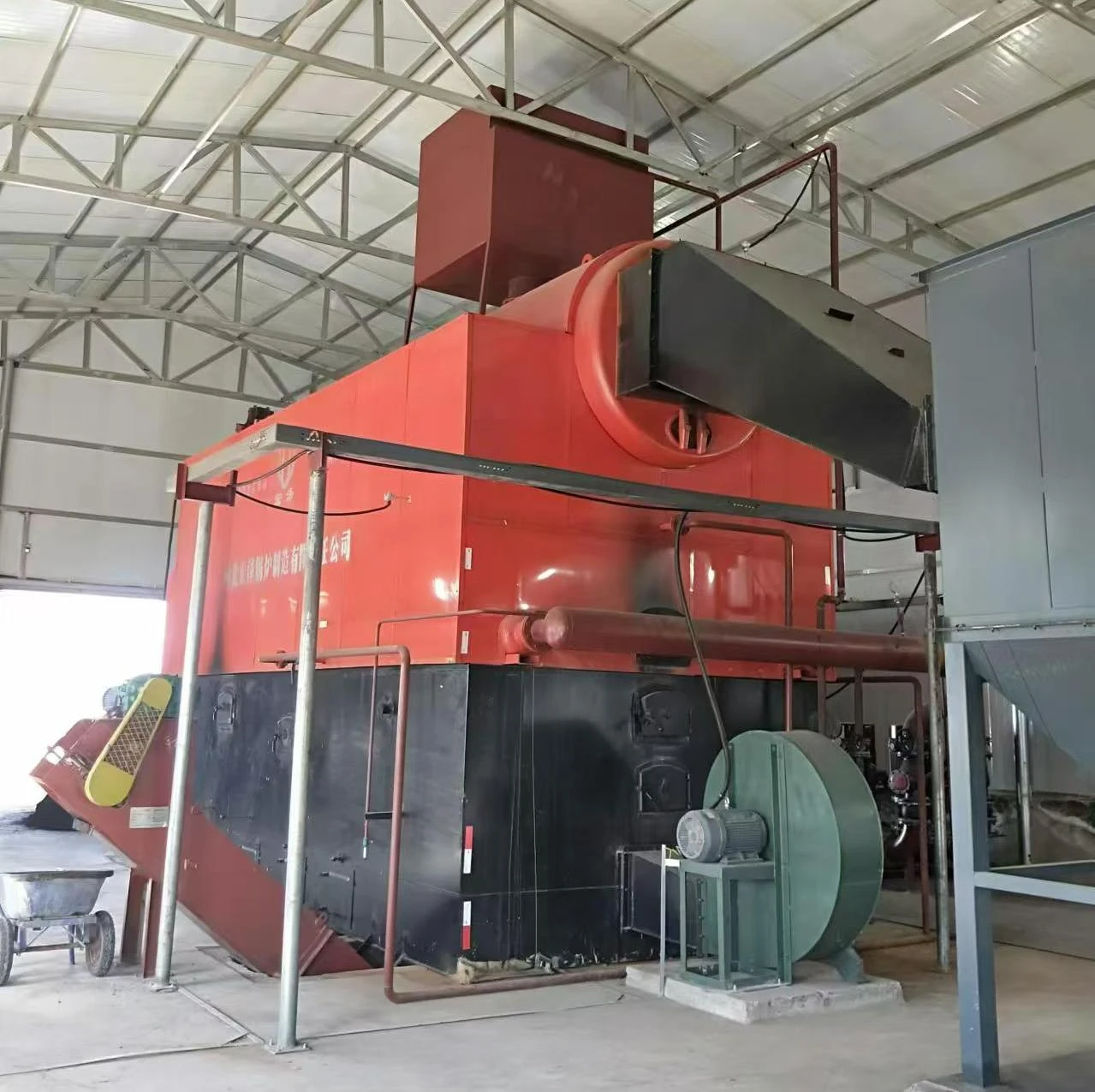
A steam boiler system is a critical component in various industrial applications, providing efficient heating and power generation. The schematic diagram of a steam boiler system serves as a vital tool for engineers and technicians, illustrating the flow of steam, water, and energy throughout the system. Understanding this diagram is essential for effective operation, maintenance, and troubleshooting.
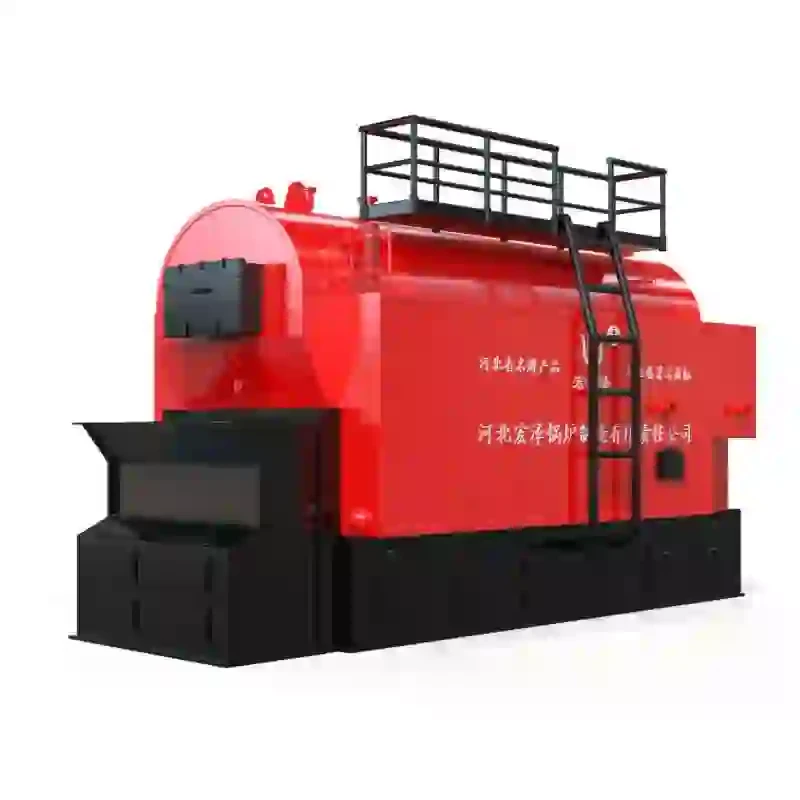
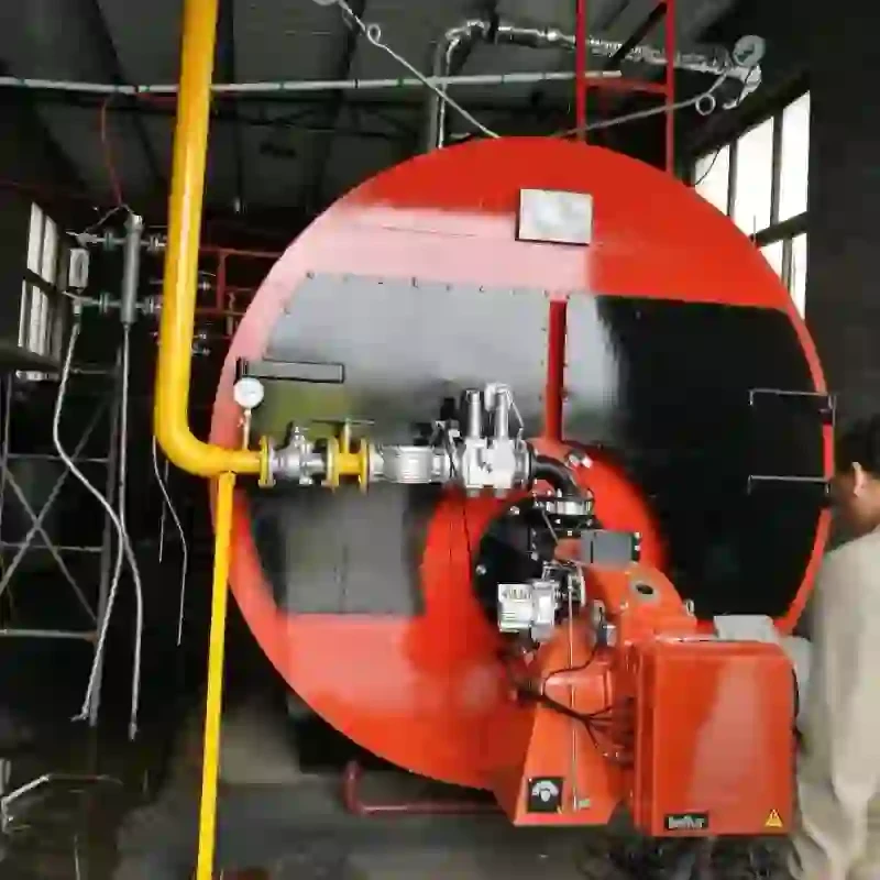
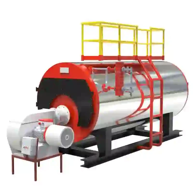
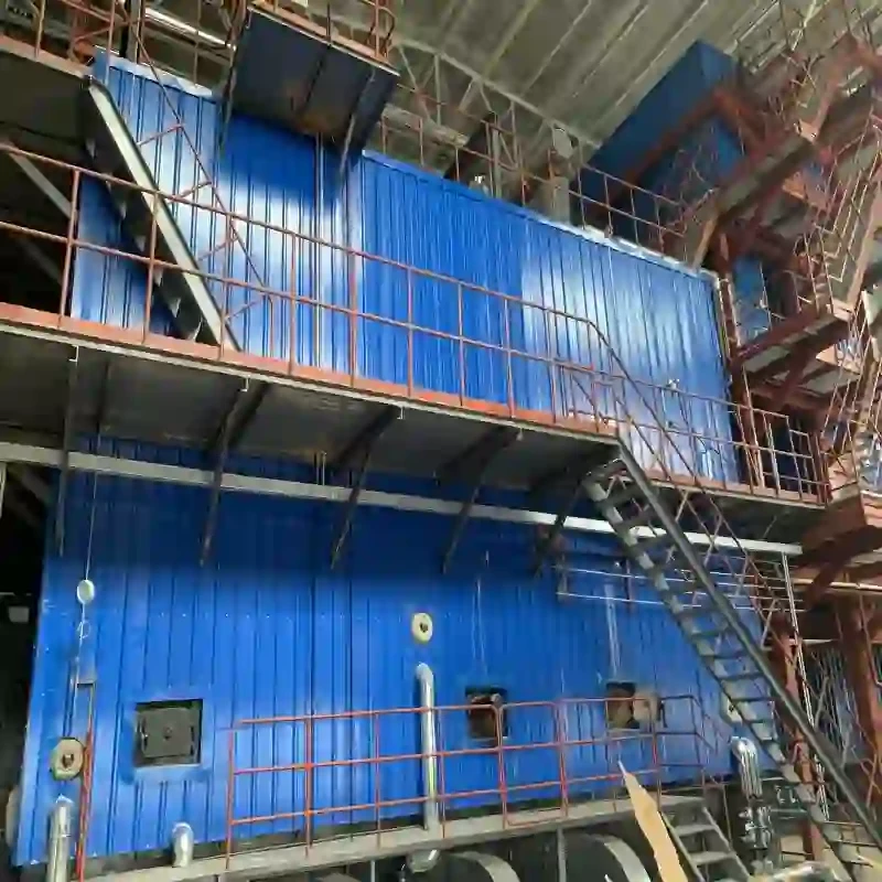
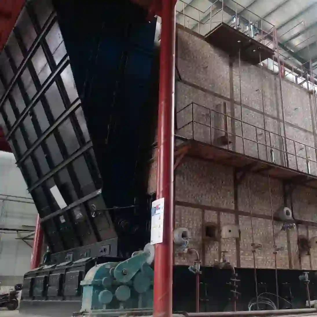
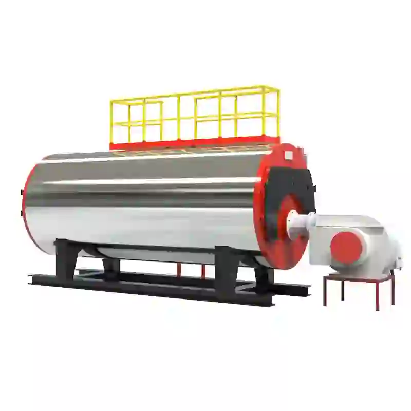
At the core of the steam boiler system is the boiler itself, a closed vessel where water is heated to produce steam. The schematic typically shows the main components, including the feed water pump, boiler, steam drum, economizer, and various valves and instruments. The feed water pump is responsible for supplying water to the boiler. This water, often processed to remove impurities, is crucial for maintaining efficiency and preventing scale buildup inside the boiler.
The diagram also includes features like the economizer, an important device that enhances the boiler's efficiency by preheating the feed water using residual heat from the flue gases. This preheating process not only conserves energy but also increases the overall system reliability. Following this, the heated water enters the boiler where it is subjected to high temperatures, converting it into steam.
steam boiler system schematic diagram

The pressure and temperature of the steam are critical parameters monitored through pressure gauges and temperature sensors depicted in the schematic. Proper regulation of these parameters ensures safe operation and maximizes the output energy. Safety valves are also illustrated, designed to relieve excess pressure and prevent dangerous situations that could lead to boiler explosions.
The steam produced is often routed to various applications, such as heating systems, turbines, or process industries. The schematic illustrates the various pipelines and control valves that manage this distribution, highlighting the need for precision in fluid movement. Control systems connected to the schematic monitor flow rates, pressure, and temperature, allowing operators to adjust the conditions for optimal performance.
Finally, the return line is shown, indicating how condensate is sent back to the boiler. This closed-loop system not only improves efficiency but also minimizes water wastage.
In conclusion, the steam boiler system schematic diagram is a fundamental representation of the complex interactions within a steam boiler system. Comprehensive knowledge of this diagram is crucial for ensuring operational efficiency, safety, and reliability in various industrial processes where steam generation plays a pivotal role. Understanding each component's function and the overall system layout ultimately leads to enhanced performance and longevity of the steam boiler system.
-
High-Efficiency Commercial Oil Fired Steam Boiler for Industry
NewsJul.30,2025
-
High-Efficiency Biomass Fired Thermal Oil Boiler Solutions
NewsJul.30,2025
-
High Efficiency Gas Fired Thermal Oil Boiler for Industrial Heating
NewsJul.29,2025
-
High-Efficiency Gas Fired Hot Water Boiler for Sale – Reliable & Affordable
NewsJul.29,2025
-
High Efficiency Biomass Fired Hot Water Boiler for Industrial and Commercial Use
NewsJul.29,2025
-
High-Efficiency Biomass Fired Hot Water Boiler for Industrial Use
NewsJul.28,2025
Related PRODUCTS


