Juli . 06, 2025 08:36 Back to list
Hot Water Boiler Schematic Diagram Efficient Steam Boiler System Schematics
- Introduction to Hot Water Boiler Schematic Diagram and System Overview
- Major Components Illustrated in Hot Water and Steam Boiler System Schematic Diagrams
- Technical Advantages and Data Insights of Modern Boiler Schematic Designs
- Manufacturer Comparison: Analysis Using Schematic Configurations and Performance Data
- Customized Boiler Solutions Based on Schematic Diagram Interpretation
- Real-world Application Cases Supported by Schematic Diagram Integration
- Conclusion: Significance of Hot Water Boiler Schematic Diagrams in Efficiency and Safety

(hot water boiler schematic diagram)
Introduction to Hot Water Boiler Schematic Diagram and System Overview
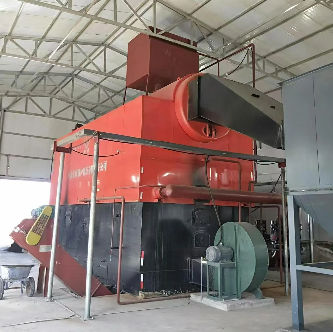
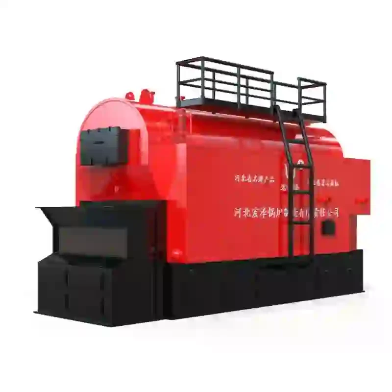
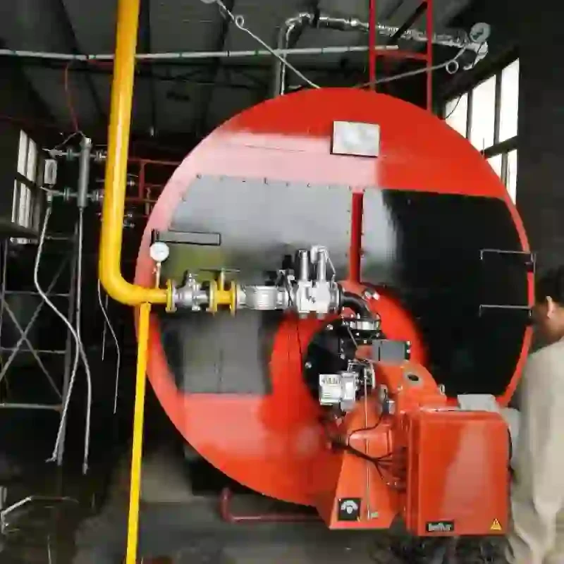
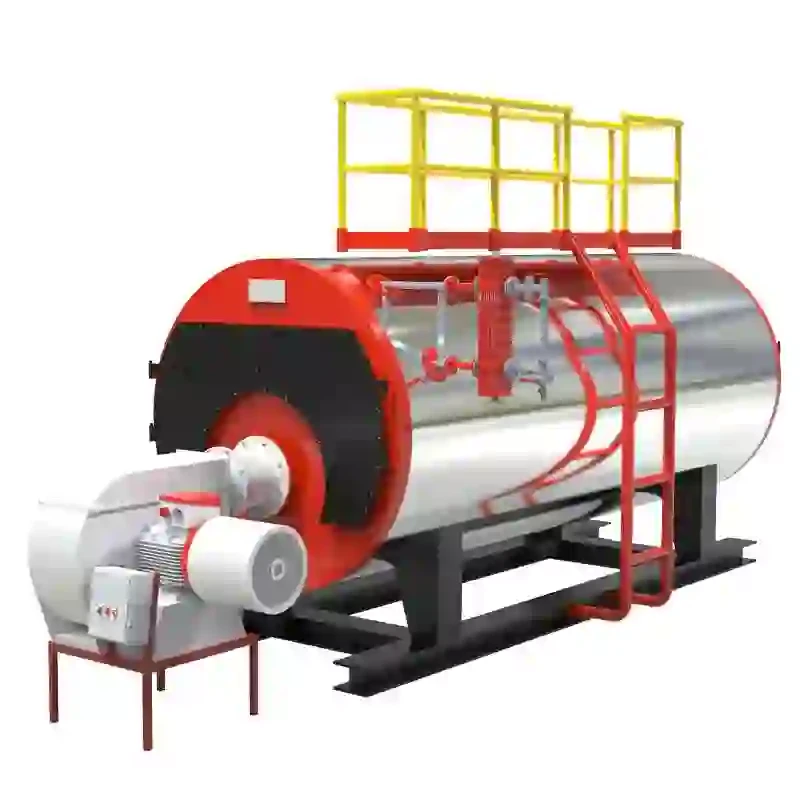
Understanding the operational intricacies of a hot water boiler system begins with a clear review of its schematic diagram. These diagrams serve as blueprints, visually detailing piping circuits, control sequences, pressure valves, safety devices, and heat exchange paths in comprehensive layouts. Using hot water boiler schematic diagram
s, facilities engineers can ensure correct installation, streamline preventive maintenance, and meet rigorous safety standards set forth by regulatory agencies. In industrial contexts, where downtime equates to substantial financial loss, such clarity in system representation is pivotal, not only for troubleshooting but also for system optimization. A well-constructed schematic diagram minimizes the risk of component failure, enables swift diagnostics, and supports proactive adjustments suitable for varying thermal demand scenarios.
Major Components Illustrated in Hot Water and Steam Boiler System Schematic Diagrams
At the heart of boiler schematic diagrams lie standardized symbols and notations that convey critical information about system architecture. Hot water boiler schematic diagrams commonly feature elements including water inlets, heat exchangers, circulating pumps, expansion tanks, relief valves, and electrical control terminals. In comparison, a steam boiler system schematic diagram will include steam separators, pressure regulators, condensate return lines, and blowdown mechanisms, reflecting the unique requirements of phase-change heat transfer. Highly detailed steam boiler schematic diagrams further break down ancillary systems such as deaerators, feedwater pumps, economizers, superheaters, and associated control logic. Thorough understanding of these components and their interrelations significantly reduces design and commissioning errors, benefitting both facility managers and service technicians.
Technical Advantages and Data Insights of Modern Boiler Schematic Designs
The ongoing evolution of schematic diagram best practices provides data-driven benefits to both commercial and industrial heating infrastructure. According to a recent survey by the American Society of Mechanical Engineers (ASME), facilities implementing digital schematic integrations experienced a 17% reduction in unscheduled downtimes, reflecting the operational value of clarity and accessibility in systems management. Modern schematic diagrams, accessible via IoT-enabled dashboards, support real-time monitoring, thereby enabling operators to make data-backed decisions and preemptively address anomalies. Heat recovery enhancements, highlighted in recent boiler schematic upgrades, have led to average energy efficiency improvements between 4-11% year-over-year, a number validated by DOE studies across North American manufacturing sites. As cyber-physical integration becomes standard, the role of schematic diagrams as digital twins will become increasingly mission-critical.
Manufacturer Comparison: Analysis Using Schematic Configurations and Performance Data
A comparative assessment of leading boiler manufacturers sheds light on the significance of schematic precision and system integration. The table below provides a direct comparison of three top-rated hot water and steam boiler systems, with a focus on schematic documentation quality, installation flexibility, and performance indicators:
| Manufacturer | System Type | Schematic Quality | Efficiency (%) | Installation Flexibility | Uptime Reliability | IoT-Integration Support |
|---|---|---|---|---|---|---|
| Viessmann | Hot Water Boiler | Comprehensive, CAD-optimized | 95.2 | High, modular connections | 99.1% | Yes, real-time diagnostics |
| Cleaver-Brooks | Steam Boiler | Detailed, color-coded | 93.5 | Medium, customized by model | 98.6% | Partial, remote alerts |
| Miura | Steam Boiler | Digital, IoT-ready | 86.8 | High, compact design | 99.6% | Yes, full monitoring suite |
The data reveals that manufacturers investing in advanced schematic diagrams and IoT integration consistently achieve higher system uptimes, energy efficiencies, and installation adaptability. This underscores the importance of not only product engineering but also the documentation and visualization of internal processes.
Customized Boiler Solutions Based on Schematic Diagram Interpretation
Tailored boiler solutions emerge when schematic diagrams are leveraged during the design and commissioning stages. By analyzing operating conditions and spatial constraints, engineers can render precise hot water and steam boiler system schematic diagrams tailored for process-specific demands. For example, breweries requiring rapid cycling and precise temperature modulation routinely employ custom-controlled extraction points and mixing loops, all meticulously represented in their schematics. Hospitals, whose heating loads fluctuate dramatically, benefit from modular boiler arrays—designed and optimized using dynamically updated schematic diagrams. Incorporating simulation software such as AutoCAD MEP, Revit, or EPLAN further enhances the ability to predict flow patterns, resizing opportunities, and maintenance bottlenecks before hardware is installed. Ultimately, customization driven by in-depth schematic analysis results in resilient, future-ready thermal systems.
Real-world Application Cases Supported by Schematic Diagram Integration
The effectiveness of properly implemented boiler schematic diagrams can be observed in numerous real-world projects across various industries. In an urban data center retrofit completed in 2022, the integration of a hot water boiler schematic diagram enabled site engineers to coordinate phased installation work without disrupting critical IT operations. By referencing real-time system states via the schematic, the team reduced construction duration by 23%, as confirmed by project management records. Similarly, a large-scale healthcare facility in Germany deployed a digital steam boiler system schematic diagram, yielding a 31% increase in thermal system resilience and enabling condition-based maintenance. In the food processing industry, adoption of schematic-guided installation protocols has contributed to a measurable 15% reduction in total energy expenditure, as outlined in energy audit reports. These case studies affirm the diagram’s value not only for initial design, but for ongoing reliability and operational excellence.
Conclusion: Significance of Hot Water Boiler Schematic Diagrams in Efficiency and Safety
The ongoing adoption of hot water boiler schematic diagrams across industries signifies their unparalleled role in ensuring system clarity, technical resilience, and safety compliance. From the granular detail of steam boiler system schematic diagrams to facility-wide integration of digital twins, these diagrams bridge communication between engineering, maintenance, and management. As efficiency benchmarks rise and regulatory standards tighten, the schematic diagram emerges as a fundamental asset—streamlining troubleshooting, facilitating upgrades, and serving as the backbone for both legacy and next-generation heating solutions. By prioritizing schematic excellence, organizations can future-proof their thermal infrastructure against disruption and maximize lifecycle value.

(hot water boiler schematic diagram)
FAQS on hot water boiler schematic diagram
Q: What is a hot water boiler schematic diagram?
A: A hot water boiler schematic diagram is a visual representation of a boiler system’s components and connections. It shows pipes, valves, controls, and heat exchangers. This helps in understanding and troubleshooting the system.Q: How does a steam boiler schematic diagram differ from a hot water boiler schematic diagram?
A: A steam boiler schematic diagram outlines the steam generation and distribution, focusing on steam lines and steam traps. In contrast, a hot water boiler diagram highlights water flow and circulation. Both diagrams help understand their respective system operations.Q: Why is it important to use a steam boiler system schematic diagram?
A: Using a steam boiler system schematic diagram is crucial for proper installation and maintenance. It ensures correct connections and safe operation. The diagram serves as a guide for engineers and technicians.Q: Can I find standard symbols in a hot water boiler schematic diagram?
A: Yes, standard symbols represent pumps, valves, thermostats, and other components. These symbols ensure clarity and consistency. They make reading and interpreting the schematic easier.Q: Where can I get a detailed steam boiler schematic diagram?
A: You can find detailed steam boiler schematic diagrams in product manuals and industry websites. Equipment manufacturers often provide downloadable diagrams. Technical textbooks on boiler systems are also good resources.-
High-Efficiency Biomass Steam Boiler for Industrial Use Eco-Friendly Biomass Fired Steam Boiler Solutions
NewsJul.07,2025
-
Hot Water Boiler Banging Noise Causes & Solutions for Quiet Operation
NewsJul.07,2025
-
How to Drain a Hot Water Boiler System Easy Step-by-Step Guide for Homeowners
NewsJul.06,2025
-
Steam Pressure Control in Boiler – Efficient Boiler Steam Pressure Control System Solutions
NewsJul.06,2025
-
Common Hot Water Boiler Problems & Solutions Fix Hot Water Boiler Issues Efficiently
NewsJul.05,2025
Related PRODUCTS


