Okt . 18, 2024 20:12 Back to list
Understanding the Components and Functionality of Steam Boiler Schematic Diagrams
Understanding the Steam Boiler Schematic Diagram
A steam boiler schematic diagram is an essential tool for engineers, technicians, and operators in the steam generation industry. It serves as a visual representation of the various components and systems within a steam boiler, allowing for easier comprehension and troubleshooting of the equipment. Understanding this schematic is crucial for effective operation and maintenance.
At its core, the steam boiler's purpose is to convert water into steam through the application of heat. This steam is then used for various applications, including heating, power generation, and industrial processes. The diagram typically includes several key components the boiler shell, burner, heat exchanger, steam drum, water feed system, and controls.
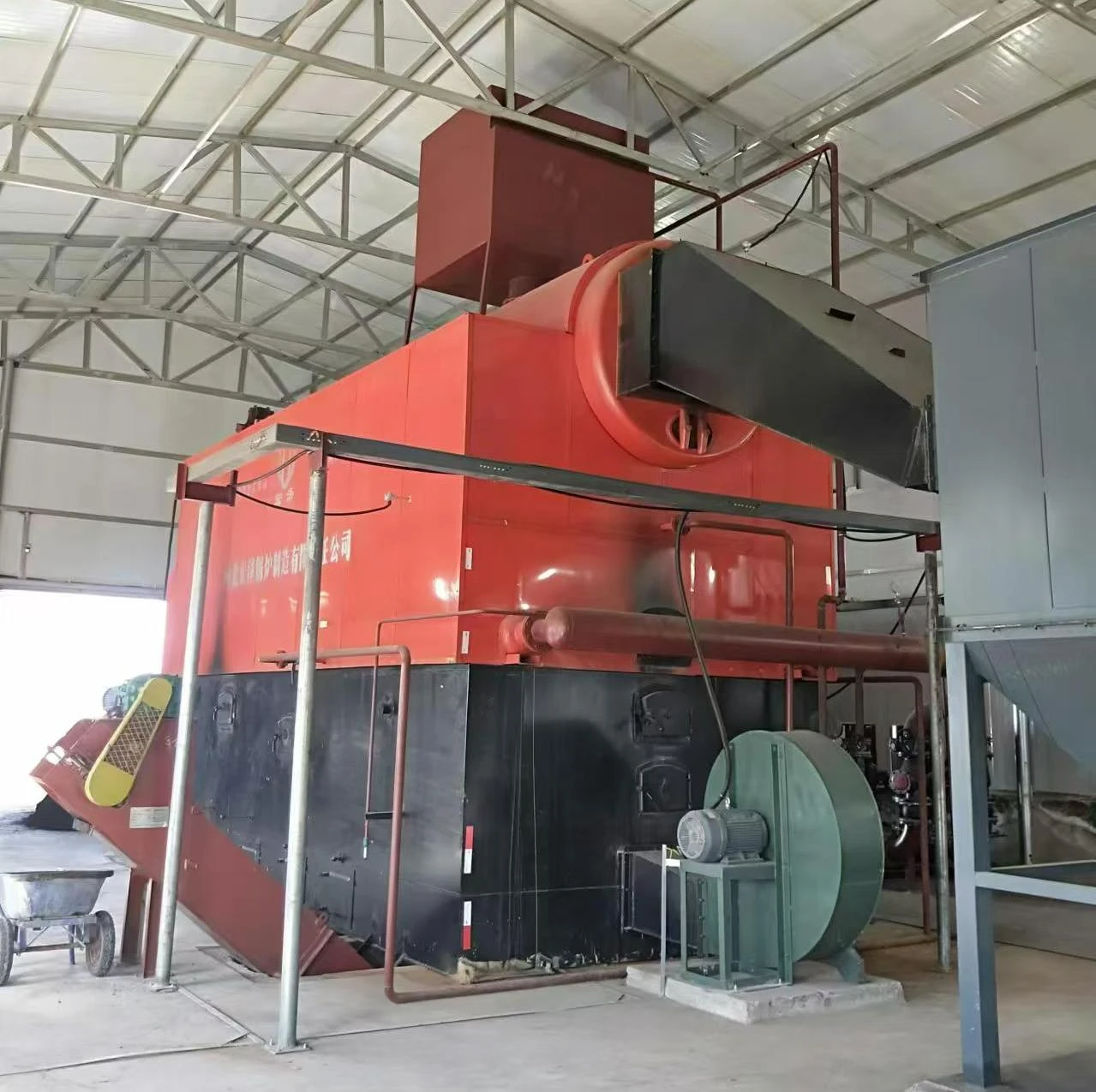
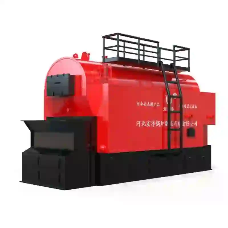
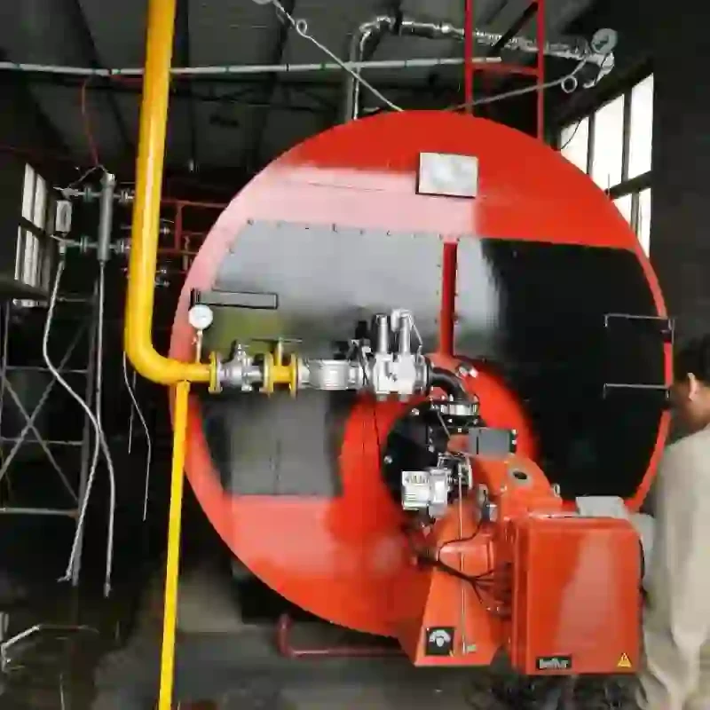
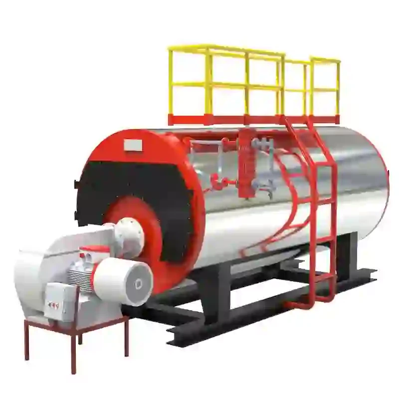
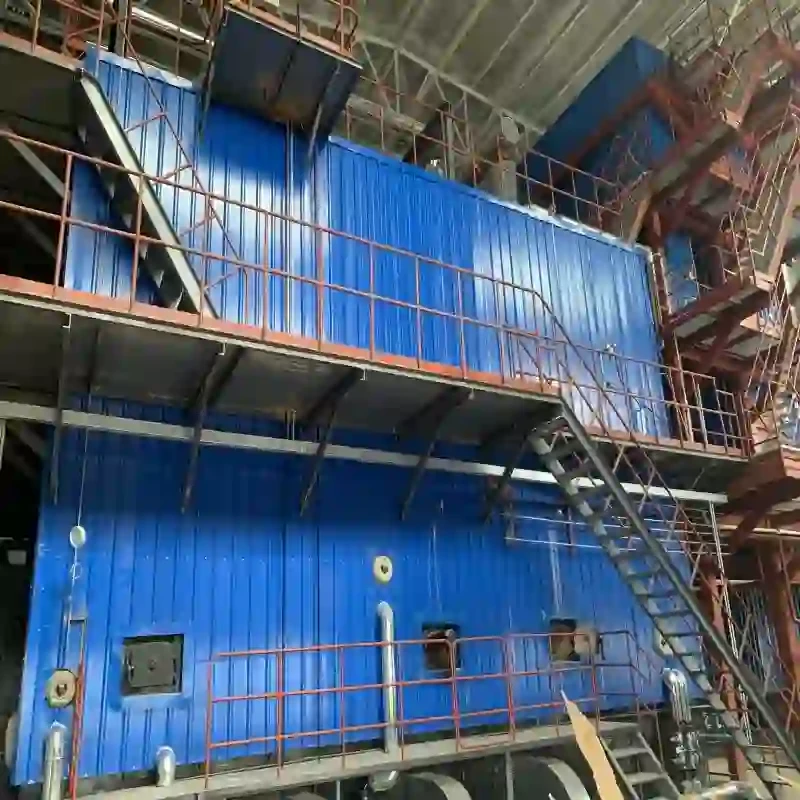
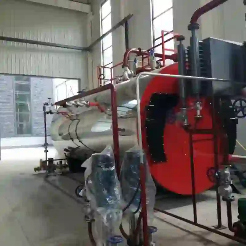
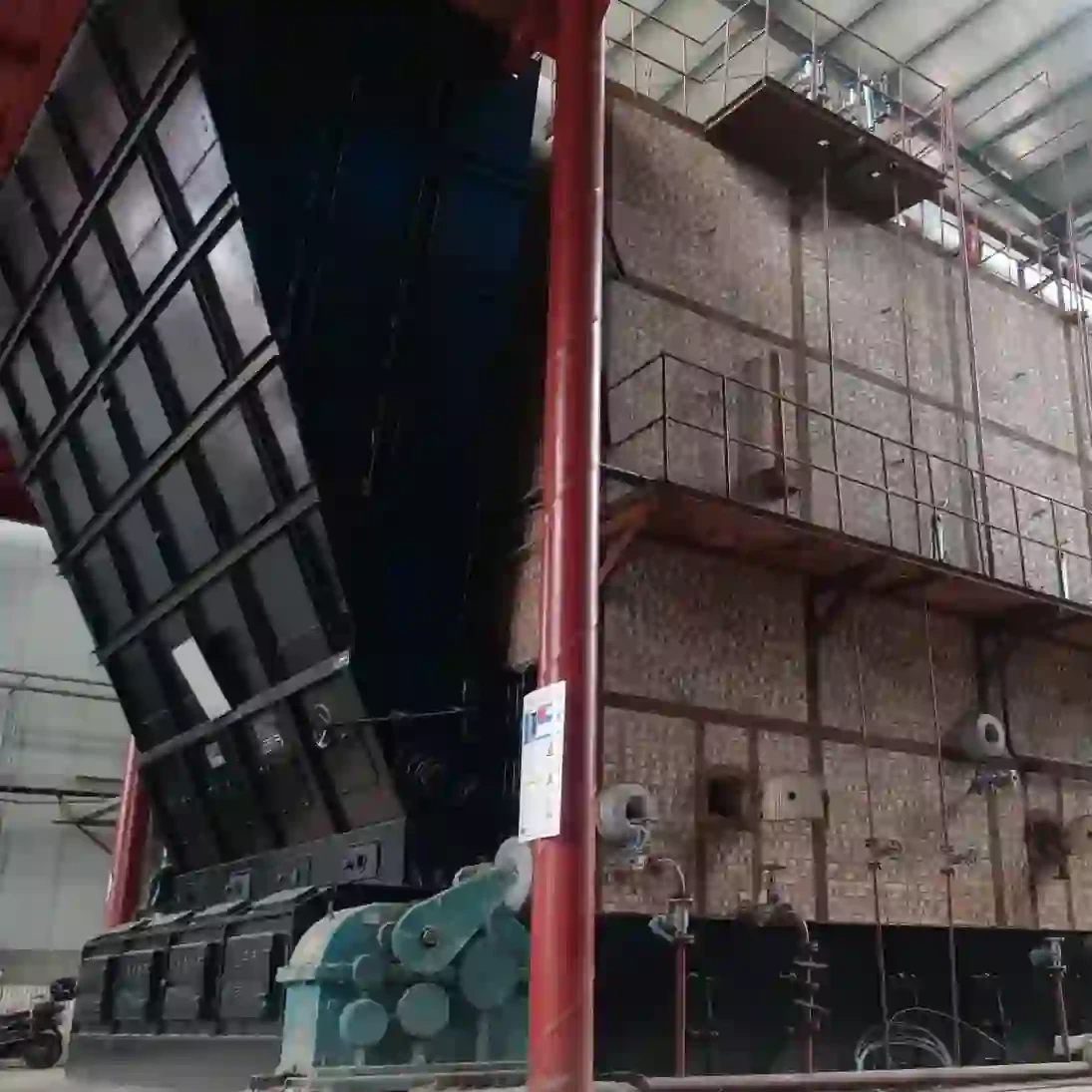
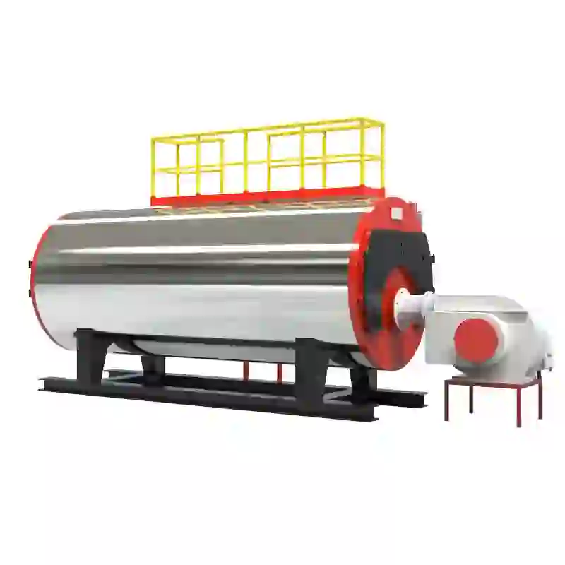
The boiler shell is the outer structure that holds the water and steam. It is usually made of steel to withstand high pressure and temperature. Inside the shell, water is heated by burners, which combust fuel—natural gas, oil, or coal—to produce heat. The burners are a critical component, as their efficiency directly impacts the boiler’s performance.
Heat generated by the burners is transferred to the water through a heat exchanger. This component allows for the efficient transfer of heat while preventing the mixing of combustible gases with steam or water. As the water absorbs heat, it begins to convert into steam, which collects in the steam drum—a crucial part of the boiler where steam separation occurs.
steam boiler schematic diagram

The water feed system is responsible for supplying the boiler with water to replace what is lost through steam generation and other processes. Typically, this system includes pumps and feedwater heaters that ensure the water enters the boiler at the appropriate temperature and pressure. Regular monitoring and maintenance of this system are vital to prevent boiler damage and ensure efficient operation.
Control systems integrated into the schematic play an essential role in the safe and efficient running of the steam boiler. They monitor parameters such as pressure, temperature, and water levels, ensuring that the boiler operates within designed limits. Alarms and automatic shut-off systems are usually included to prevent unsafe conditions, enhancing operational safety.
Additionally, the schematic diagram may include safety devices, such as pressure relief valves and water level indicators, which are crucial for preventing accidents. These components are designed to protect the boiler from excessive pressure and ensure consistent performance, contributing to the overall reliability of the system.
In conclusion, a steam boiler schematic diagram provides a comprehensive overview of the various components and their interactions within a steam boiler system. Understanding this diagram is vital for anyone involved in the operation, maintenance, or design of steam boilers. Effective interpretation of the schematic can lead to improved efficiency, safety, and longevity of the equipment, ultimately delivering reliable steam for a variety of industrial applications. Whether you are an experienced engineer or new to the field, familiarizing yourself with a steam boiler schematic will enhance your understanding of these essential systems.
-
Efficient Biomass Fired Hot Water Boiler | AI Heating Solution
NewsAug.01,2025
-
High-Efficiency Gas Thermal Oil Boilers | HPT Models
NewsJul.31,2025
-
Oil Fired Hot Water Boilers Sale - High Efficiency & Affordable
NewsJul.31,2025
-
High-Efficiency Commercial Oil Fired Steam Boiler for Industry
NewsJul.30,2025
-
High-Efficiency Biomass Fired Thermal Oil Boiler Solutions
NewsJul.30,2025
-
High Efficiency Gas Fired Thermal Oil Boiler for Industrial Heating
NewsJul.29,2025
Related PRODUCTS


