Nov. . 04, 2024 18:52 Back to list
steam boiler schematic diagram
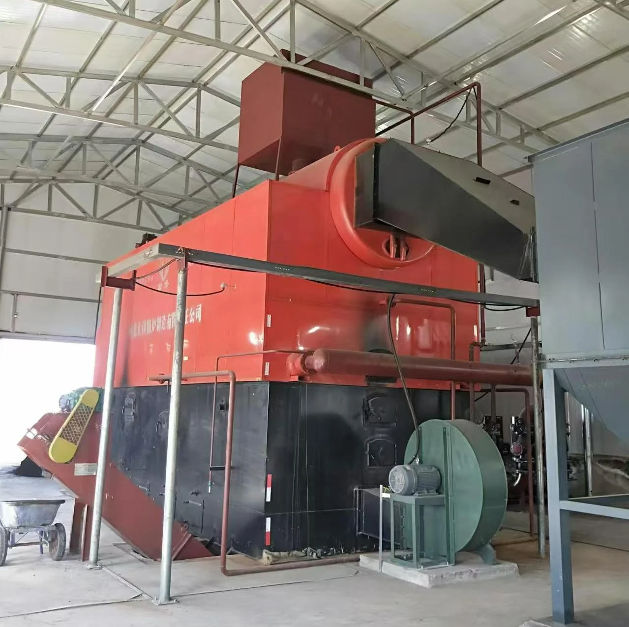
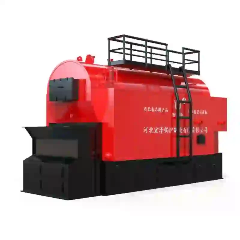
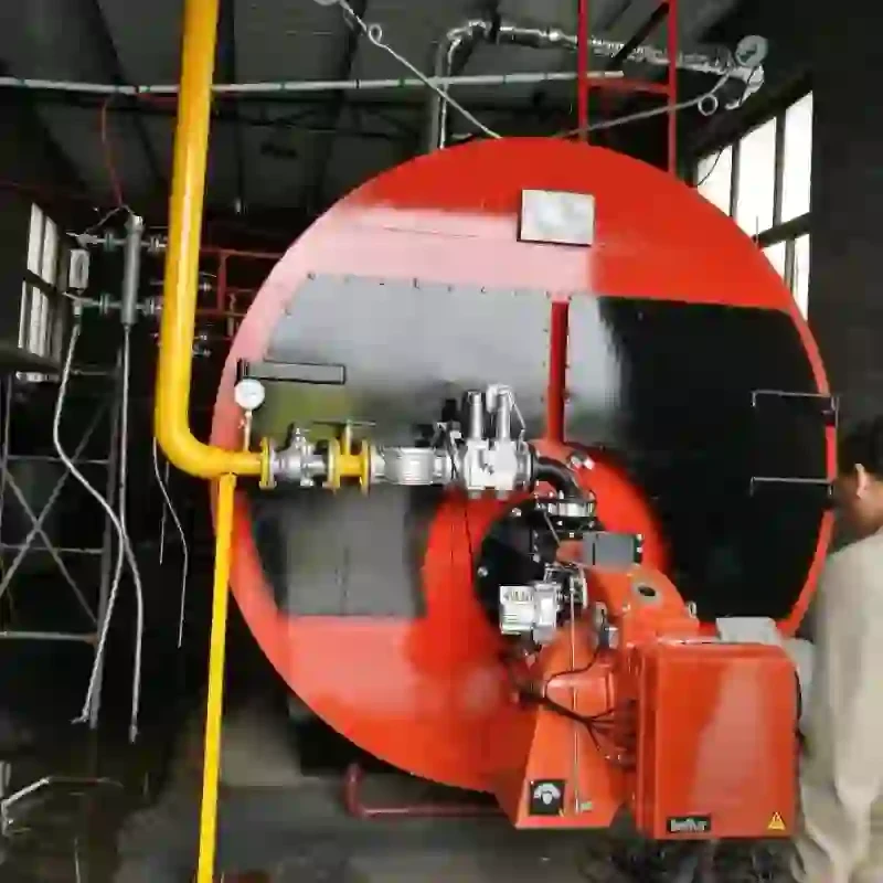
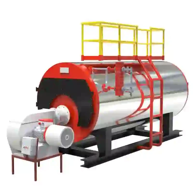
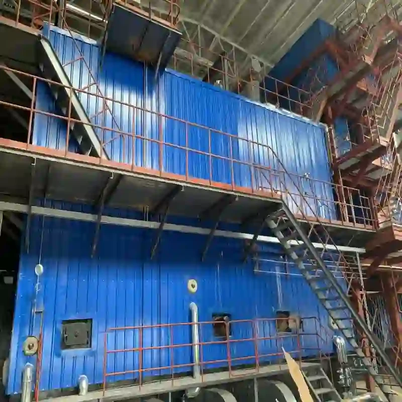
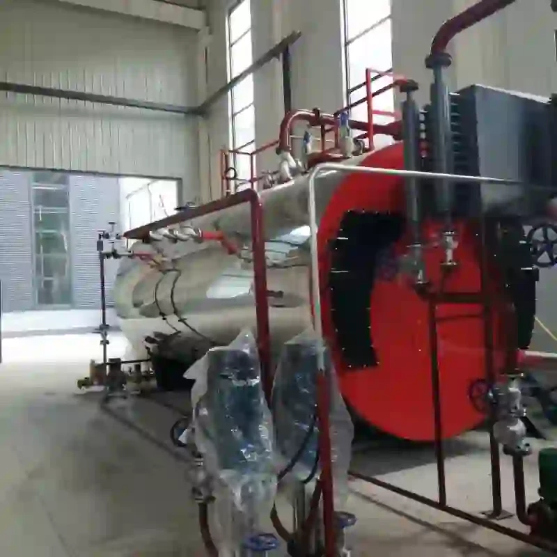
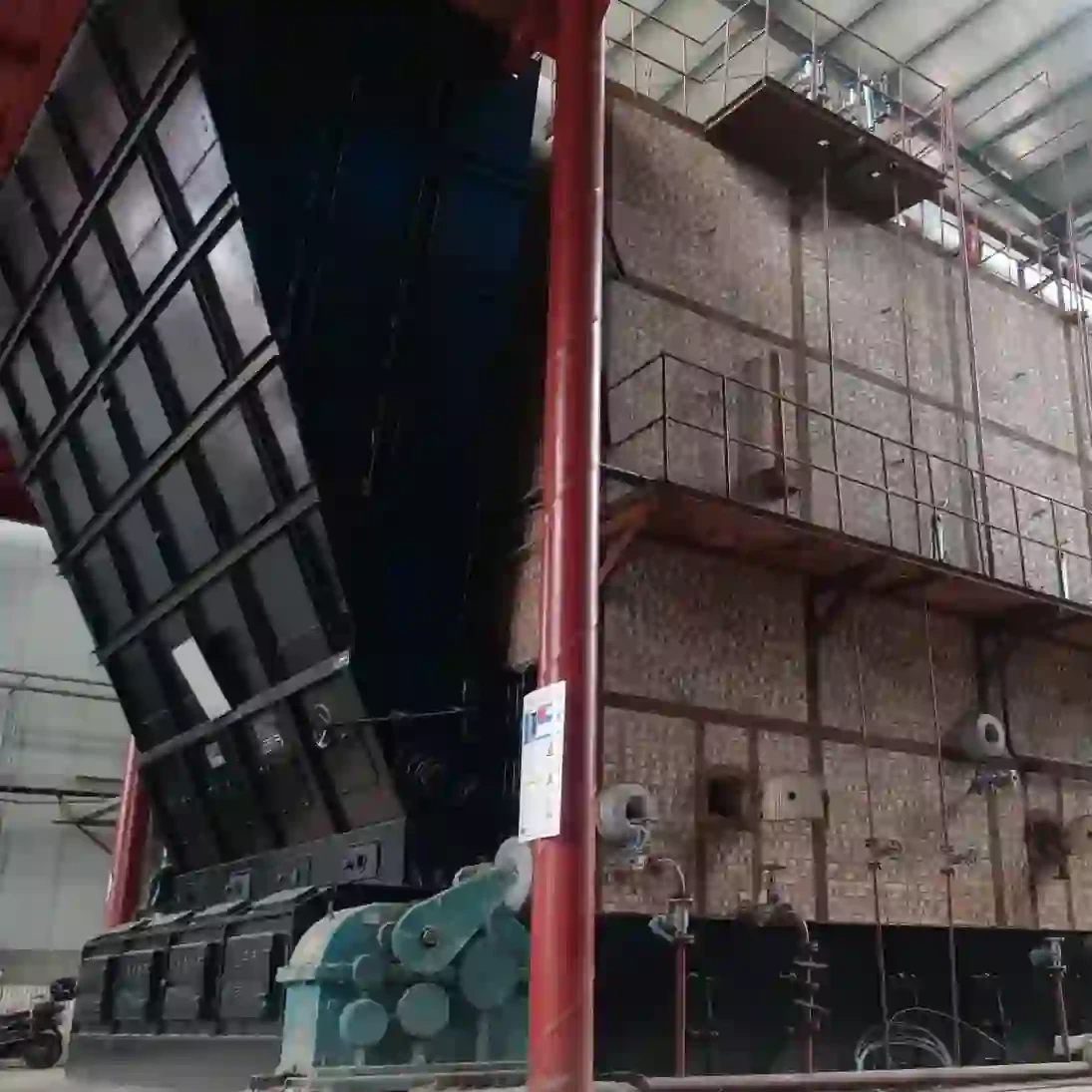
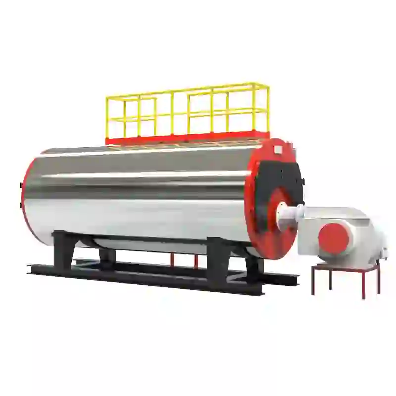
A steam boiler plays a crucial role in various industrial processes, serving as a key component for generating steam that drives turbines, heats substances, and powers machinery. Understanding the schematic diagram of a steam boiler is essential for engineers and technicians alike, as it provides a clear visual representation of its components and their operational relationships.
At the core of the steam boiler is the combustion chamber, where fuel, such as natural gas, coal, or oil, is burned to produce heat. The heat generated then heats water contained in the boiler's vessels. In the schematic diagram, this chamber is usually depicted at the top, illustrating the flow of exhaust gases that exit through a flue. The efficiency of this combustion process is critical, as optimum fuel usage ensures minimal environmental impact and cost-effective operation.
The boiler typically consists of several key components, including the feedwater system, the steam drum, the safety valves, and the blowdown system. The feedwater system is responsible for delivering water to the boiler, which is often pre-treated to remove impurities. In the schematic, this system is illustrated with pipes leading into a water inlet, often situated at the base of the boiler.
The steam drum is another vital part depicted in the schematic, functioning as the storage area for steam generated from water. This drum separates steam from the water and ensures that only saturated steam (steam with a proper quality) is sent to the distribution system. The schematic will show outlet pipes leading from the steam drum to various locations within the facility, where steam is utilized.
steam boiler schematic diagram

Safety is paramount in boiler operations, and this is reflected in the schematic diagram through the inclusion of safety valves. These valves are critical for preventing excessive pressure buildup, automatically releasing steam if the pressure exceeds a certain limit. A reliable blowdown system, illustrated in the diagram, helps maintain water quality by removing sludge and impurities that accumulate at the bottom of the boiler.
Moreover, a good schematic diagram will illustrate auxiliary components such as pumps, economizers, and controls, which optimize the boiler's performance and efficiency. Collectively, these elements communicate how a steam boiler operates, providing insights into the system's efficiency, safety, and maintenance requirements.
In conclusion, a steam boiler schematic diagram serves as an invaluable tool for understanding the inner workings of these essential systems. By efficiently converting water into steam, the boiler supports numerous industrial applications, making it vital for both operation and engineering practices. Understanding its schematic layout enables better troubleshooting, optimization, and maintenance, ultimately leading to enhanced productivity and safety within the industry.
-
High-Efficiency Commercial Oil Fired Steam Boiler for Industry
NewsJul.30,2025
-
High-Efficiency Biomass Fired Thermal Oil Boiler Solutions
NewsJul.30,2025
-
High Efficiency Gas Fired Thermal Oil Boiler for Industrial Heating
NewsJul.29,2025
-
High-Efficiency Gas Fired Hot Water Boiler for Sale – Reliable & Affordable
NewsJul.29,2025
-
High Efficiency Biomass Fired Hot Water Boiler for Industrial and Commercial Use
NewsJul.29,2025
-
High-Efficiency Biomass Fired Hot Water Boiler for Industrial Use
NewsJul.28,2025
Related PRODUCTS


