Қаз . 09, 2024 13:44 Back to list
Steam Boiler System Overview and Schematic Diagram for Efficient Operations
Understanding Steam Boiler Schematics
Steam boilers are crucial components in various industries, providing essential steam for processes such as heating, power generation, and cleaning. Understanding the schematic of a steam boiler can help operators and engineers ensure optimal performance and safety.
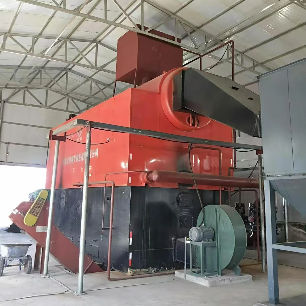
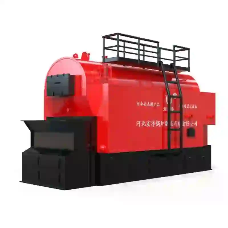
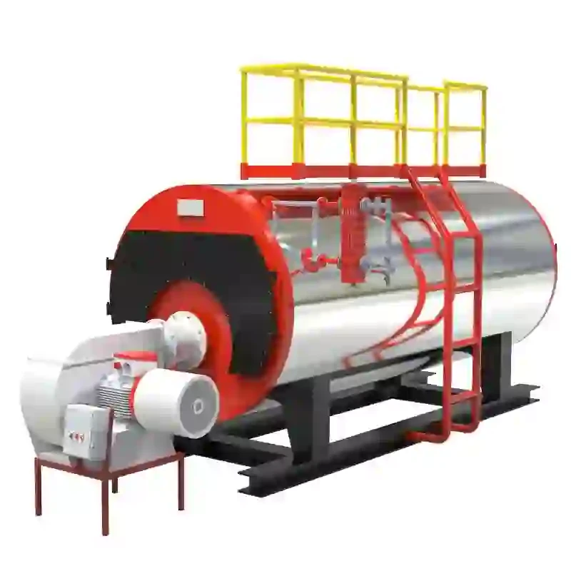
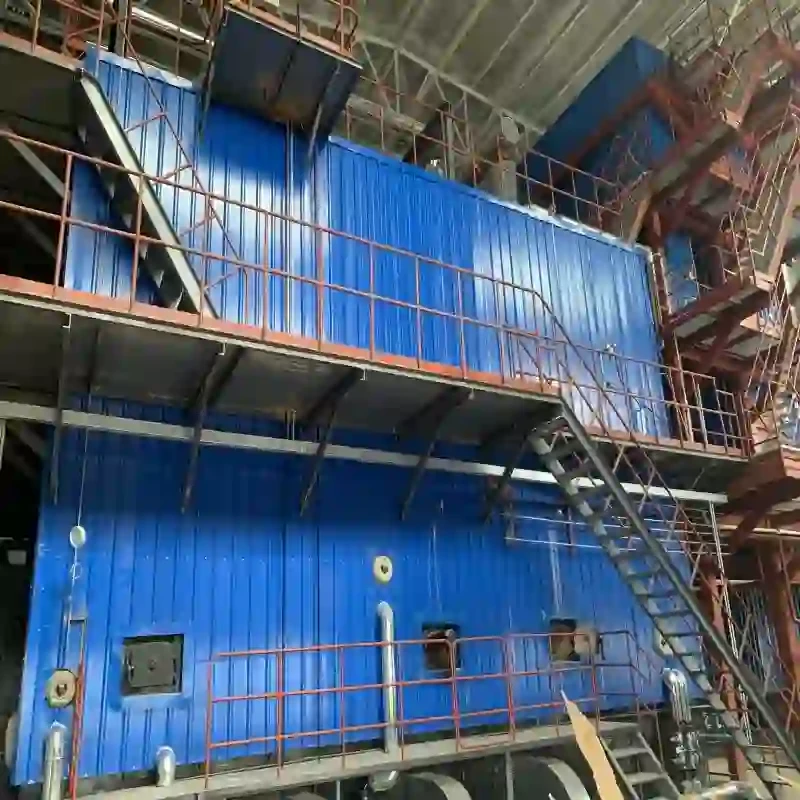
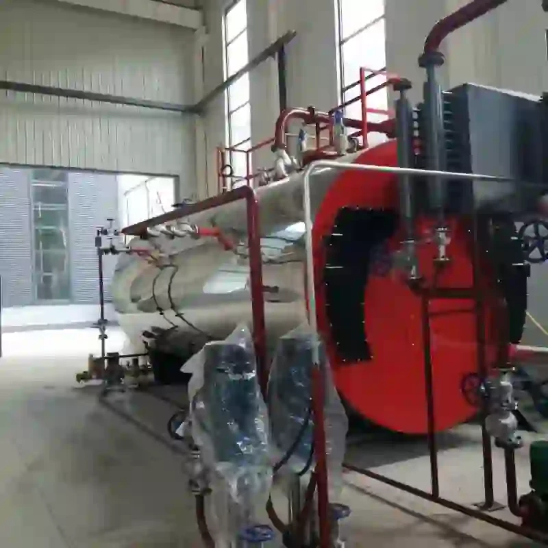
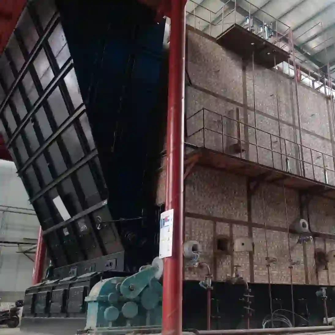
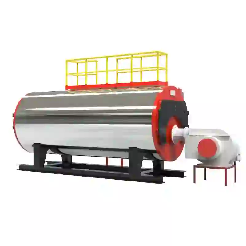
A steam boiler schematic typically includes various parts, each serving a specific function in the overall operation of the system. At its core, a steam boiler consists of a pressure vessel where water is heated to produce steam. The schematic will typically illustrate the following key components
1. Boiler Shell The outer structure that houses all internal components. It is designed to withstand high pressure, with materials selected for their strength and heat resistance.
2. Furnace The area where fuel combustion occurs. Whether using natural gas, oil, or coal, the fuel burns in the furnace, creating hot gases that heat the water in the boiler shell.
3. Heat Exchanger This component maximizes the efficiency of the boiler by transferring heat from the combustion gases to the water without allowing the two to mix. It plays a critical role in increasing energy efficiency.
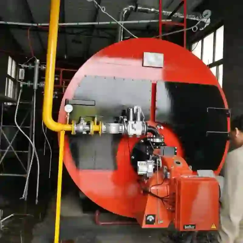
4. Burner The device that controls the combustion process, including fuel and air supply. A well-functioning burner contributes to optimized performance and reduced emissions.
steam boiler schematic
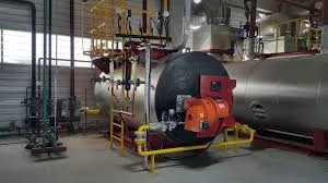
5. Steam Outlet The pipe through which steam leaves the boiler for use in processes. This should be properly insulated to minimize heat loss.
6. Water Inlet and Feed Water Pump This system supplies water to the boiler. The feed water pump maintains the water level within the boiler, ensuring consistent steam production.
7. Safety Valve An essential safety feature that releases steam if pressure exceeds safe limits, preventing potential explosions.
8. Pressure Gauge An instrument that monitors the pressure within the boiler. Regular checks ensure that the pressure remains within safe operational limits.
The schematic also includes various control systems that automate and monitor the boiler's operation. These may involve electronic controls, feedback loops, and data logging systems to provide real-time insights into performance and efficiency.
Understanding how these components interact helps in diagnosing issues and performing maintenance. Operators should familiarize themselves with the schematic, be aware of the boiler’s operational parameters, and periodically review safety protocols to avoid accidents.
In conclusion, a steam boiler schematic serves as a foundational tool for understanding the complexities of steam generation. By grasping the function of each component and how they interrelate, operators can ensure safe, efficient, and reliable boiler operation, ultimately contributing to the overall efficiency of the industrial processes they support.
-
High-Efficiency Gas Thermal Oil Boilers | HPT Models
NewsJul.31,2025
-
Oil Fired Hot Water Boilers Sale - High Efficiency & Affordable
NewsJul.31,2025
-
High-Efficiency Commercial Oil Fired Steam Boiler for Industry
NewsJul.30,2025
-
High-Efficiency Biomass Fired Thermal Oil Boiler Solutions
NewsJul.30,2025
-
High Efficiency Gas Fired Thermal Oil Boiler for Industrial Heating
NewsJul.29,2025
-
High-Efficiency Gas Fired Hot Water Boiler for Sale – Reliable & Affordable
NewsJul.29,2025
Related PRODUCTS


