តុលា . 06, 2024 10:57 Back to list
steam boiler system schematic diagram
Understanding the Steam Boiler System Schematic Diagram
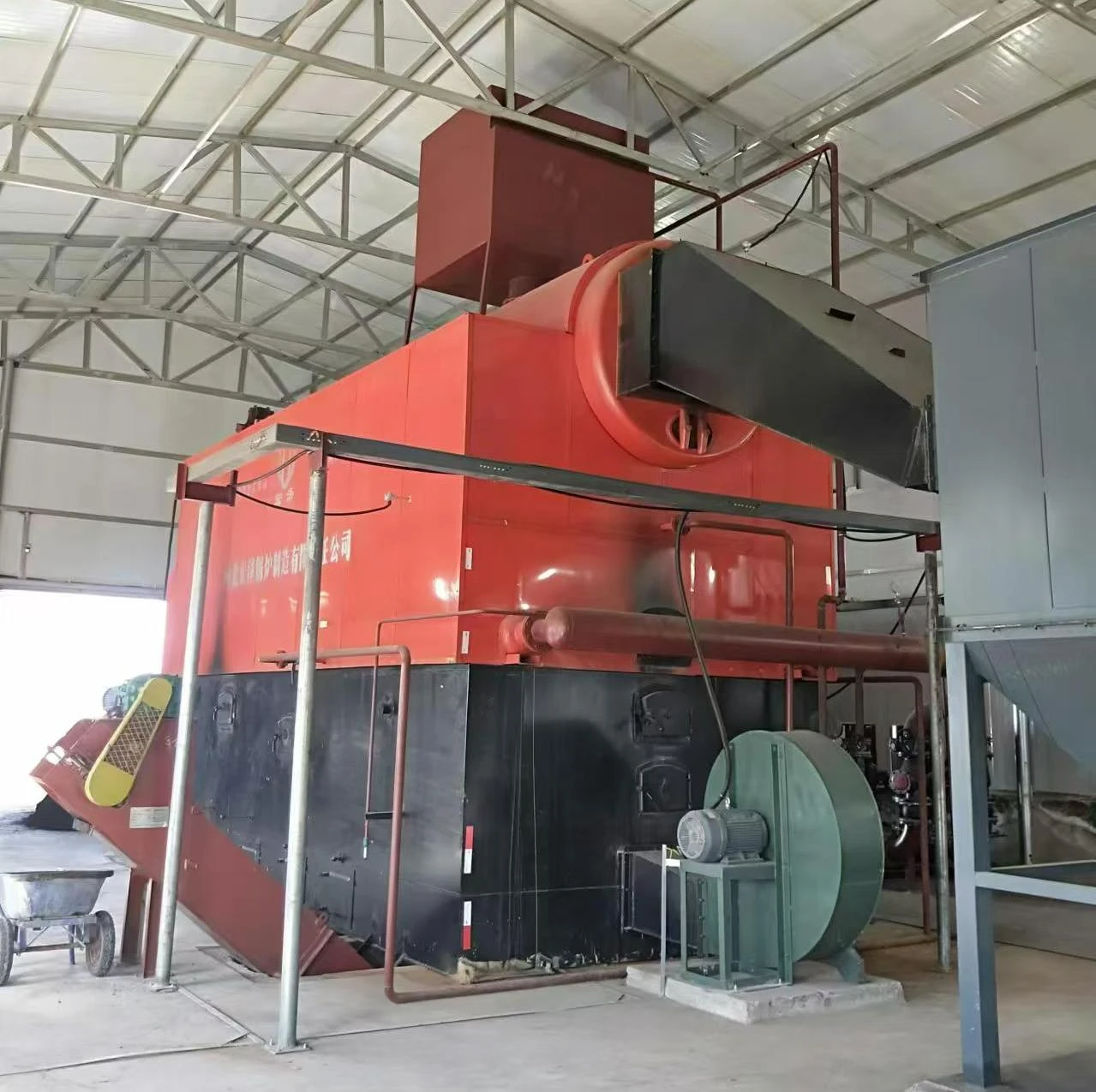
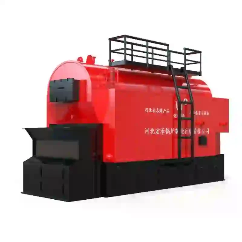
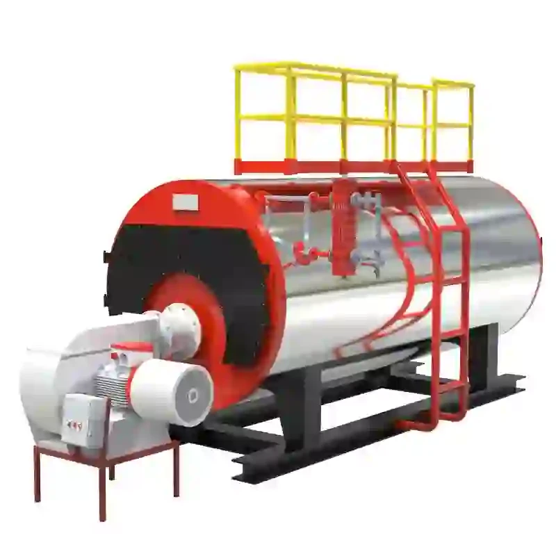
A steam boiler system plays a crucial role in various industrial applications, generating steam for heating, power generation, and other processes. Understanding its schematic diagram can significantly enhance one’s ability to maintain, troubleshoot, and optimize boiler operations. This article delves into the fundamental components and functionalities of a steam boiler system, as illustrated in typical schematic diagrams.
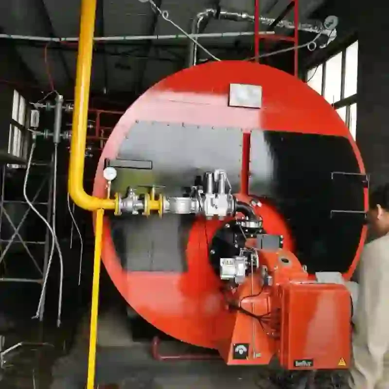
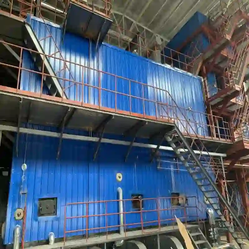
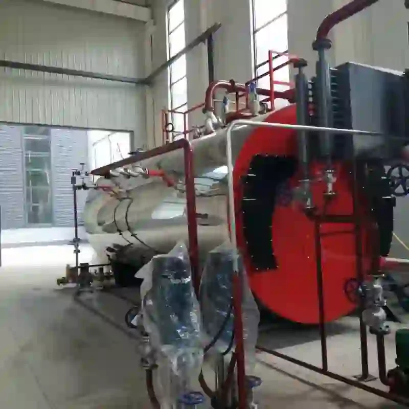
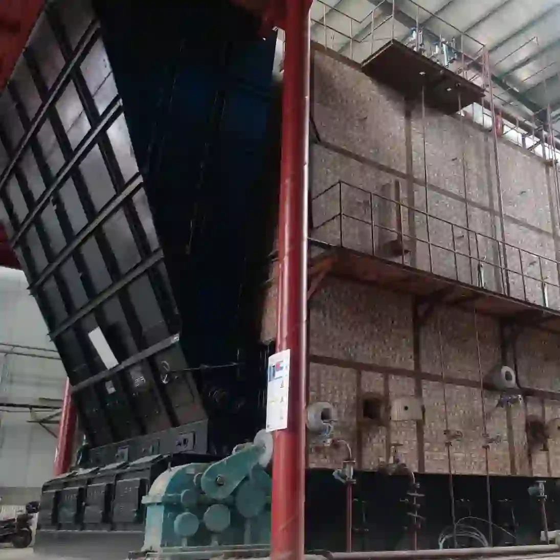
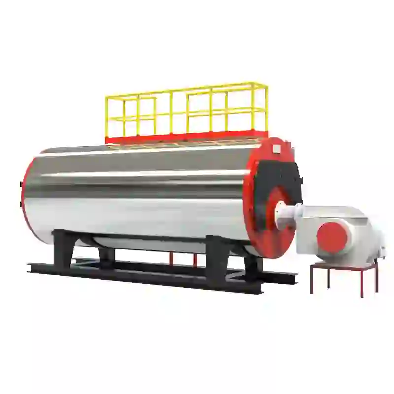
At the heart of the steam boiler system is the boiler itself, where water is heated to produce steam. The schematic diagram typically depicts the boiler’s key components, including the burner, combustion chamber, heat exchanger, and water level indicators. The burner is responsible for igniting the fuel—be it natural gas, oil, or biomass—fueling the combustion process within the chamber, which generates heat.
The schematic also shows the water inlet and steam outlet piping. The water inlet is connected to a feedwater system that supplies fresh water to the boiler, ensuring continuous steam production. On the other hand, the steam outlet directs the generated steam to various processes or systems requiring heat or power. Properly balancing these flows is essential for efficient boiler operation.
steam boiler system schematic diagram

Another vital element often highlighted in the schematic is the economizer. This device recycles exhaust heat from the flue gases back into the feedwater, improving the overall efficiency of the system. By preheating the water, the economizer reduces energy consumption and lowers operational costs.
Safety devices are also prominently featured in boiler system diagrams. These include pressure relief valves and water level controls. The pressure relief valve is critical for preventing overpressure scenarios that could lead to catastrophic failures, while water level controls ensure the boiler operates within safe water level parameters. This is essential to avoid dry firing, which can cause severe damage to the boiler.
Additional components often found in the schematic include blowdown valves, which help remove sediments and impurities that accumulate in the boiler, thus maintaining its efficiency and prolonging its lifespan. Additionally, instrumentation for monitoring temperature, pressure, and flow rates is essential for operators to ensure the system functions effectively.
In summary, understanding a steam boiler system schematic diagram involves recognizing the various components and their interrelationship. Each element, from the burner to safety devices, plays a pivotal role in ensuring the system operates efficiently and safely. Mastery of these diagrams not only aids in effective operation but also enhances the ability to troubleshoot and optimize the steam boiler system, contributing to improved industrial productivity. As industries continue to evolve, so too will the technology and methods associated with steam boiler systems, underscoring the need for ongoing education in this critical field.
-
Efficient Biomass Fired Hot Water Boiler | AI Heating Solution
NewsAug.01,2025
-
High-Efficiency Gas Thermal Oil Boilers | HPT Models
NewsJul.31,2025
-
Oil Fired Hot Water Boilers Sale - High Efficiency & Affordable
NewsJul.31,2025
-
High-Efficiency Commercial Oil Fired Steam Boiler for Industry
NewsJul.30,2025
-
High-Efficiency Biomass Fired Thermal Oil Boiler Solutions
NewsJul.30,2025
-
High Efficiency Gas Fired Thermal Oil Boiler for Industrial Heating
NewsJul.29,2025
Related PRODUCTS


