វិច្ឆិកា . 02, 2024 02:11 Back to list
steam boiler system schematic diagram
Understanding the Steam Boiler System Schematic Diagram
A steam boiler system is a critical component in various industrial and residential applications, providing essential heating and power generation. Understanding its schematic diagram is vital for engineers, technicians, and operators involved in maintaining and optimizing the efficiency of these systems.
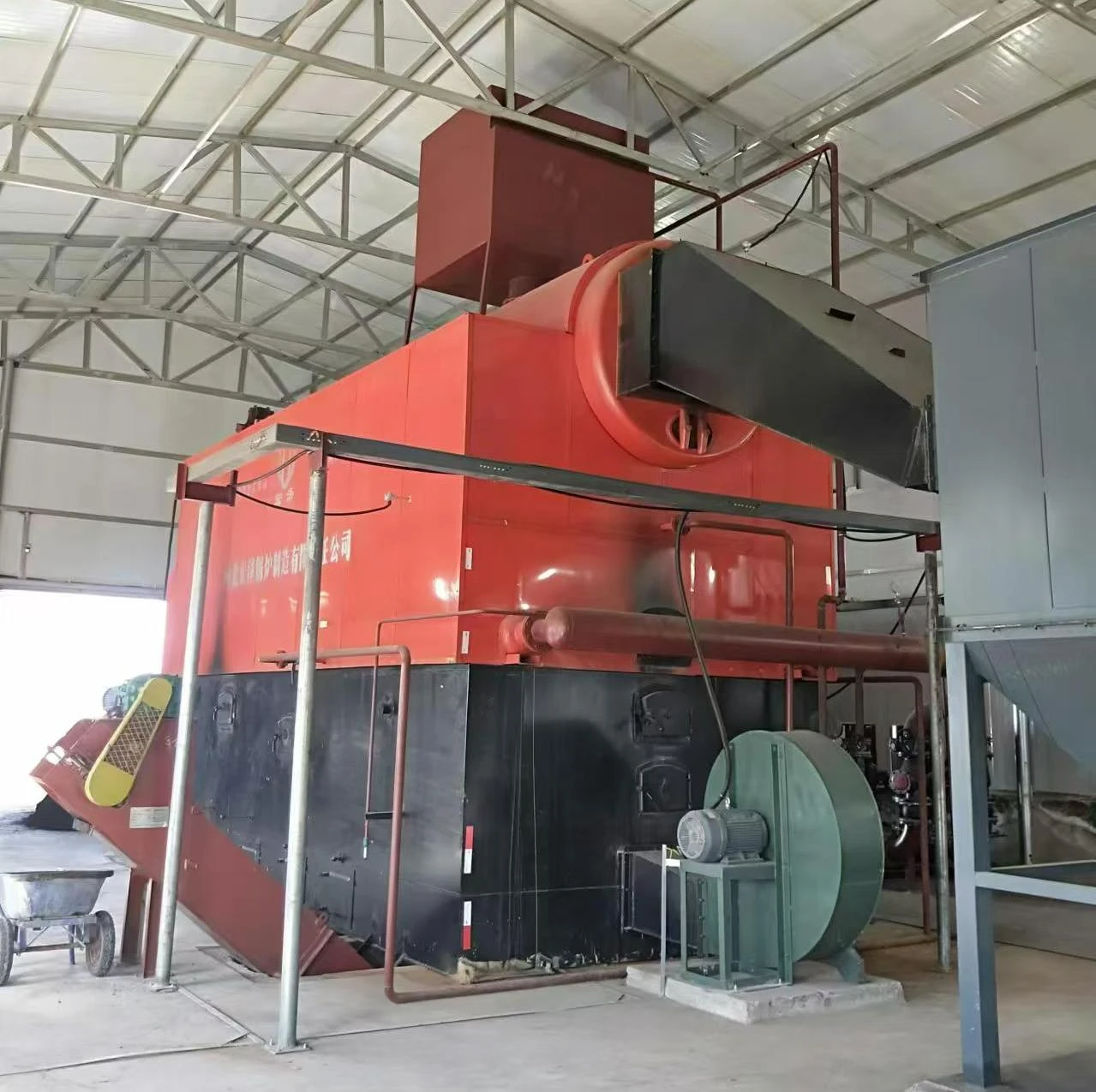
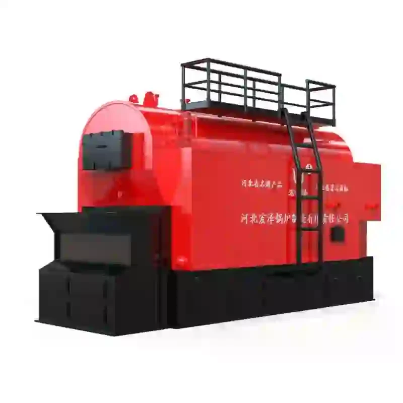
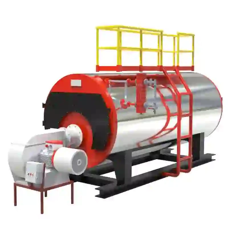
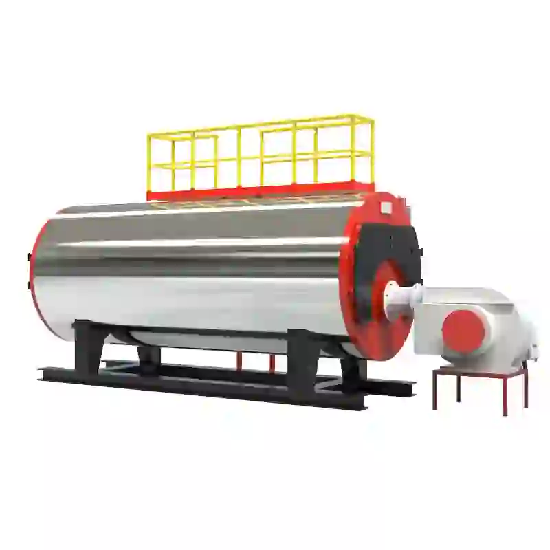
At the core of the schematic diagram is the steam boiler itself. This device is designed to convert water into steam through the application of heat generated by burning fuel or using electricity. The schematic typically depicts various sections and components, including the combustion chamber, heat exchangers, water feed system, and steam outlets.
1. Basic Components of a Steam Boiler System
The schematic diagram commonly includes several key components
- Boiler Drum This is the main vessel where water is heated to produce steam. The drum is designed to withstand high pressure and is equipped with safety mechanisms to prevent overheating and pressure buildup.
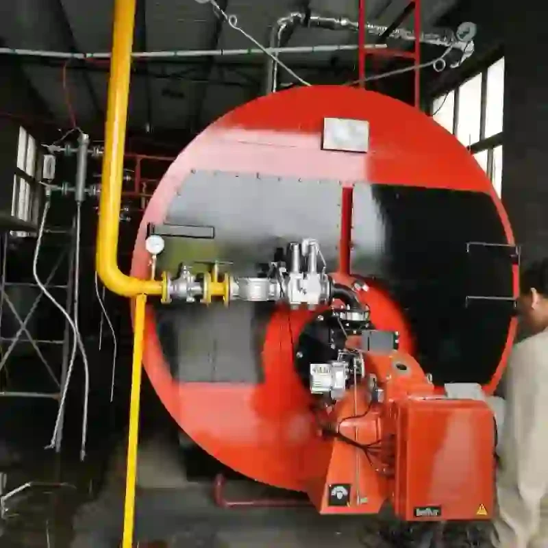
- Fuel Supply System Depending on the type of boiler, the fuel supply can vary from natural gas, oil, or coal. The schematic illustrates how fuel enters the combustion chamber and the controls that regulate fuel flow and air supply for efficient burning.
- Burner The burner is responsible for mixing the fuel with air and igniting it. The combustion process generates heat which is transferred to the water inside the boiler drum.
- Heat Exchanger This component helps transfer the heat from the combustion gases to the water
. In some designs, the heat exchanger also captures waste heat for further energy recovery, improving overall system efficiency.steam boiler system schematic diagram

- Steam Outlet Once steam is generated, it is routed through the steam outlet. The schematic shows the valves and piping that control the flow of steam to various applications, such as heating systems, turbines, or process equipment.
2. System Controls and Safety Mechanisms
The schematic diagram also incorporates various controls and safety features. These include
- Pressure Control Devices such as pressure gauges and relief valves ensure the steam remains within safe operational limits. If pressure exceeds predetermined levels, safety valves release steam to prevent potential explosions.
- Water Level Control Maintaining proper water levels is crucial for safe operation. The schematic will show level indicators and automatic feedwater systems that replenish water within the boiler.
- Temperature Controls Thermostats and temperature gauges help monitor the heat output, allowing operators to adjust the firing rate of the burner as necessary.
3. Maintenance and Troubleshooting
Interpreting the schematic diagram is also essential for maintenance and troubleshooting. Understanding each component's role allows technicians to identify issues such as leaks, inefficiencies, or safety hazards. Regular inspections, along with a comprehensive understanding of the schematic, enable operators to keep the steam boiler system running smoothly and safely.
In conclusion, the steam boiler system schematic diagram provides a detailed overview of the components and processes involved in steam generation. A clear understanding of this diagram is essential for efficient operation, ensuring safety and reliability in industrial and residential applications. Proper maintenance and adherence to operational guidelines based on schematic interpretations can significantly enhance the performance and longevity of steam boilers.
-
High-Efficiency Commercial Oil Fired Steam Boiler for Industry
NewsJul.30,2025
-
High-Efficiency Biomass Fired Thermal Oil Boiler Solutions
NewsJul.30,2025
-
High Efficiency Gas Fired Thermal Oil Boiler for Industrial Heating
NewsJul.29,2025
-
High-Efficiency Gas Fired Hot Water Boiler for Sale – Reliable & Affordable
NewsJul.29,2025
-
High Efficiency Biomass Fired Hot Water Boiler for Industrial and Commercial Use
NewsJul.29,2025
-
High-Efficiency Biomass Fired Hot Water Boiler for Industrial Use
NewsJul.28,2025
Related PRODUCTS


