12월 . 20, 2024 18:50 Back to list
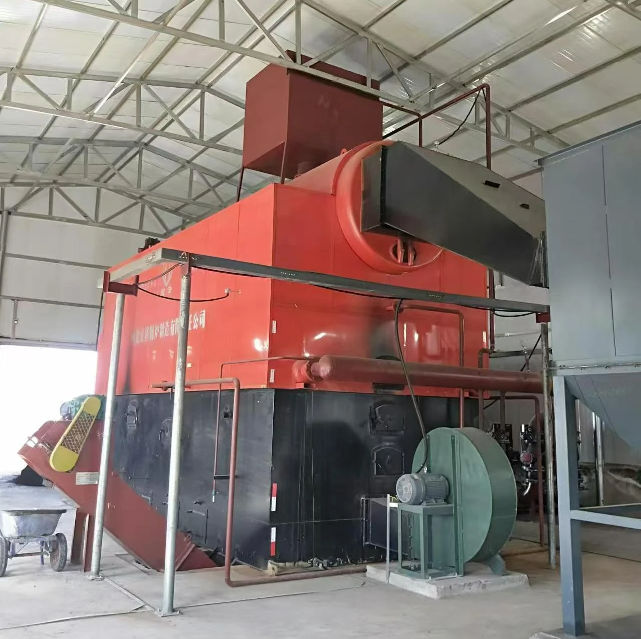
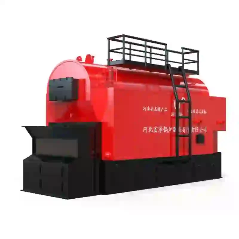
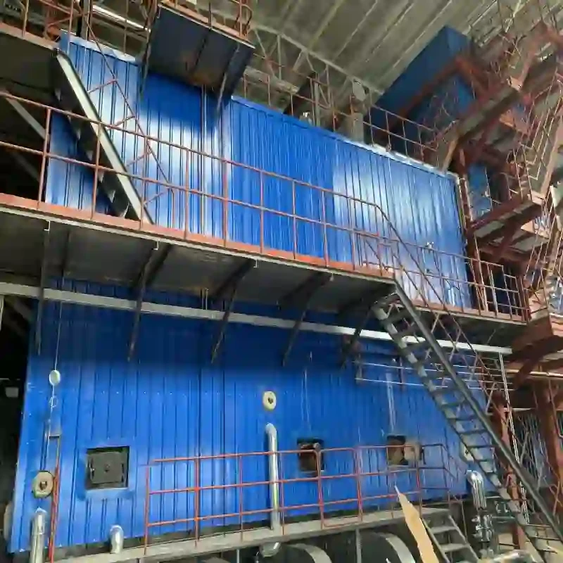
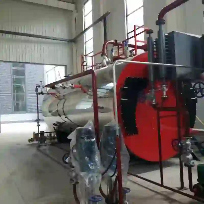
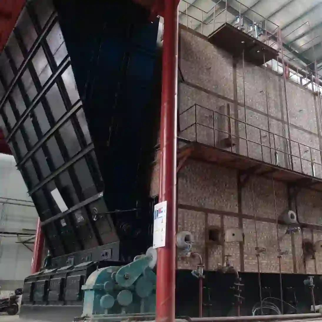
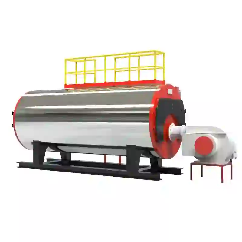
diagram of steam boiler
Understanding the Diagram of a Steam Boiler
Steam boilers are critical components in a wide array of industrial processes and heating applications. They convert water into steam through a complex series of physical and thermodynamic processes. A well-designed boiler diagram provides insight into the intricate workings of this essential machinery, showcasing how various parts interact to produce steam efficiently and safely.
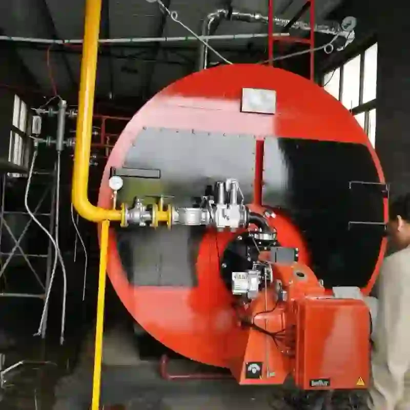
At the core of a steam boiler is the combustion chamber, where fuel is burned to generate heat. The design of the combustion chamber is crucial, as it must facilitate thorough fuel combustion while maximizing heat transfer to the water. Depending on the type of boiler, fuels can range from natural gas and oil to biomass and coal. The efficiency of this process is influenced by factors such as air-to-fuel ratio and the design of the burner, which is typically depicted in the boiler diagram.
Understanding the Diagram of a Steam Boiler
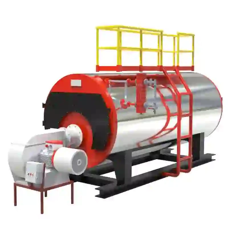
One of the essential components shown in a steam boiler diagram is the steam drum. This is the vessel where steam collects before it is directed out for use. The steam drum serves as a separation point where steam rises to the top, while water remains at the bottom. Inside the drum, separators can be employed to ensure that only dry steam exits, minimizing the risk of water carryover, which can damage downstream equipment.
diagram of steam boiler

To control pressure within the boiler, safety valves are an integral part of the design. These valves are crucial for preventing the boiler from exceeding its rated pressure, which could lead to catastrophic failures. The schematic will show the placement of these valves, typically located near the steam drum, ready to relieve excess pressure quickly.
Additionally, a steam boiler typically includes a feedwater system. This system is responsible for supplying water to the boiler—often controlled by feedwater pumps—which ensure that the right amount of water is maintained to meet steam generation needs. The feedwater is treated to prevent scaling and corrosion, ensuring the longevity of the boiler.
A heat exchanger, or economizer, may also be included in the diagram, showcasing its role in improving energy efficiency. An economizer captures residual heat from the exhaust gases and uses it to preheat the incoming feedwater. This not only conserves energy but also reduces fuel consumption, aligning with modern standards for sustainability and cost-effectiveness.
Other components often depicted include blow-off valves, which allow for the removal of sediments that accumulate in the boiler, and instrumentation for monitoring pressure, temperature, and flow rates. These instruments are vital for maintaining operational control and ensuring the safety of the steam generation process.
In conclusion, the diagram of a steam boiler serves as an essential tool for understanding its functions and components. It visually depicts how various parts work synergistically to produce steam efficiently and safely. From the combustion chamber to the steam drum, and through the feedwater system to the heat exchanger, each element plays a crucial role in the overall operation of the steam boiler. As industries increasingly prioritize efficiency and sustainability, understanding these diagrams will be essential for engineers, technicians, and operators involved in the design and operation of steam systems.
-
Commercial Steam Boilers for Sale - AI Optimized Efficiency
NewsAug.02,2025
-
Efficient Biomass Fired Hot Water Boiler | AI Heating Solution
NewsAug.01,2025
-
High-Efficiency Gas Thermal Oil Boilers | HPT Models
NewsJul.31,2025
-
Oil Fired Hot Water Boilers Sale - High Efficiency & Affordable
NewsJul.31,2025
-
High-Efficiency Commercial Oil Fired Steam Boiler for Industry
NewsJul.30,2025
-
High-Efficiency Biomass Fired Thermal Oil Boiler Solutions
NewsJul.30,2025
Related PRODUCTS


