12월 . 04, 2024 12:18 Back to list
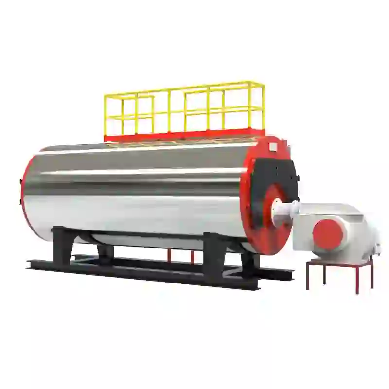
schematic diagram of steam boiler
Understanding the Schematic Diagram of a Steam Boiler
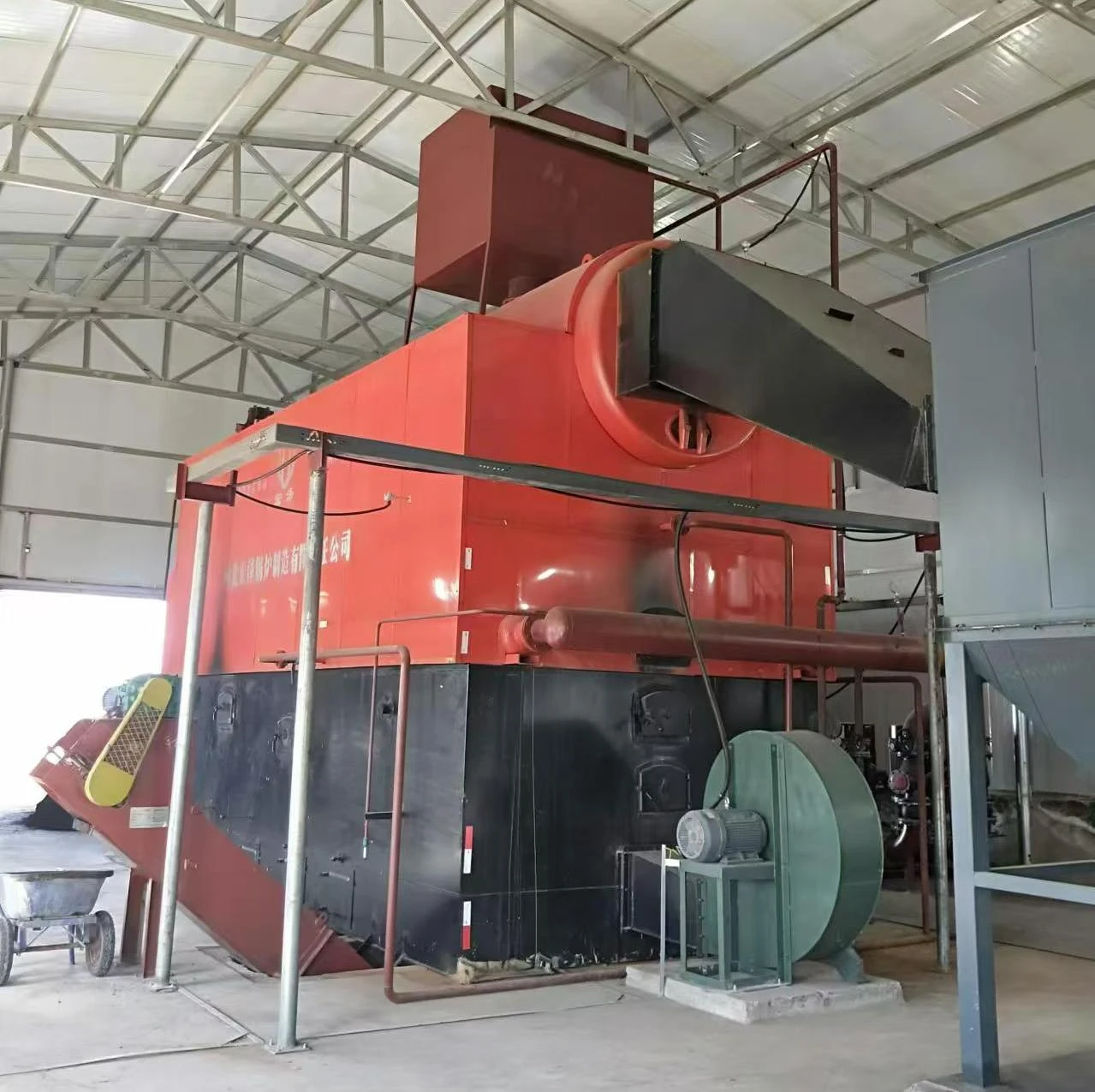
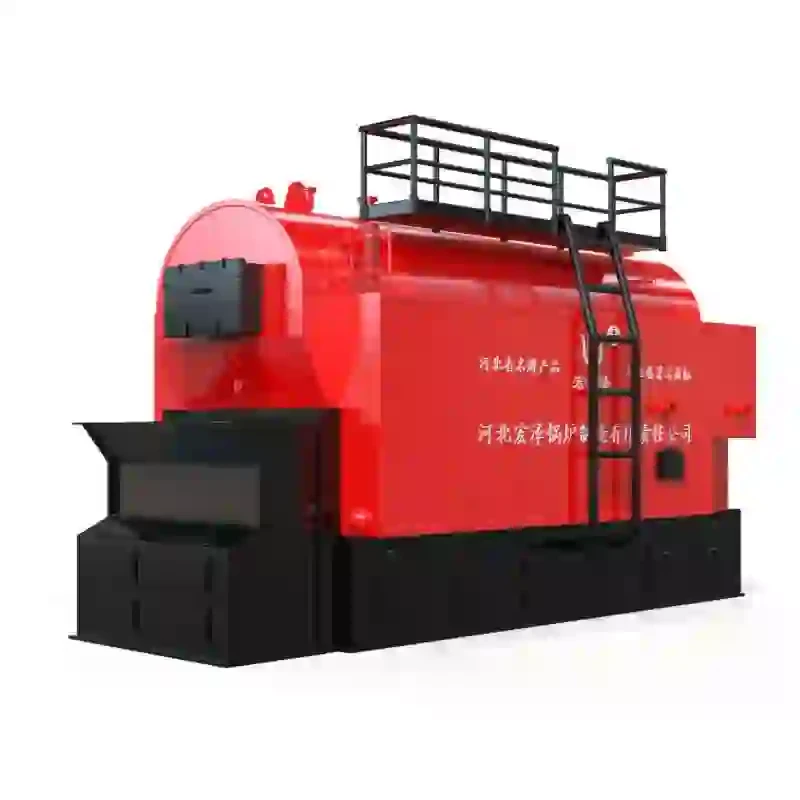
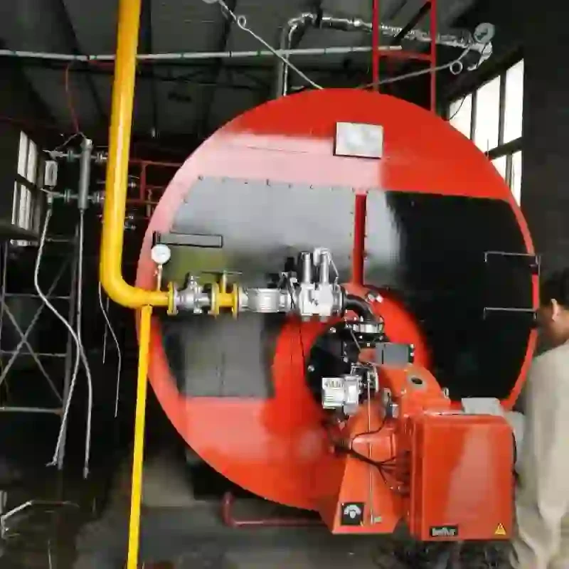
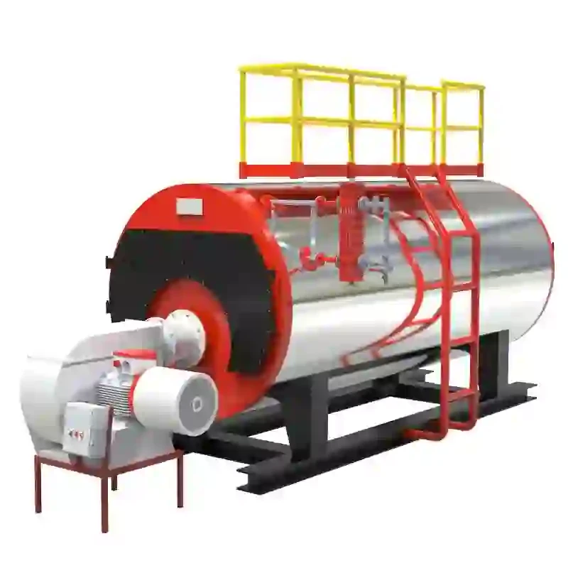
A steam boiler is an essential component in various industrial and residential applications, responsible for generating steam by heating water. The schematic diagram of a steam boiler provides a detailed representation of its components and the flow of fluids within the system. This diagram is crucial for engineers and technicians, as it facilitates understanding, maintenance, and troubleshooting of the boiler system. In this article, we will explore the key elements of a steam boiler schematic diagram and their functions.
Components of a Steam Boiler Schematic Diagram
1. Boiler Shell The boiler shell is the outer structure that contains the water and steam. It is typically made of steel or cast iron and is designed to withstand high pressure and temperature.
2. Furnace The furnace is the combustion chamber where fuel is burned to produce heat. The heat generated is transferred to the water in the boiler. Different types of fuel can be used, including natural gas, oil, coal, or biomass.
3. Water Inlet The water inlet is the entry point for water that fills the boiler. It is vital that the water quality is maintained to prevent scaling and corrosion inside the boiler.
4. Steam Outlet The steam outlet is where the generated steam exits the boiler to be distributed throughout the system for various applications, such as heating processes, turbine drives, or sterilization.
5. Pressure Gauge This device measures the pressure of the steam within the boiler. Monitoring the pressure is critical for the safe and efficient operation of the boiler.
7. Water Level Indicator This component shows the water level inside the boiler. Maintaining the correct water level is essential to prevent damage to the boiler and ensure efficient steam production.
schematic diagram of steam boiler

8. Blow-off Valve This valve discharges accumulated sediment and impurities from the bottom of the boiler. Regular blow-off helps maintain water quality and prevents sludge buildup.
9. Feedwater Pump The feedwater pump is responsible for delivering water into the boiler, ensuring a continuous supply for steam generation.
10. Economizer An economizer preheats the feedwater using flue gas heat, improving the overall efficiency of the boiler. By utilizing waste heat, it reduces fuel consumption and operational costs.
11. Flue Gas Path The pathway for flue gases generated during combustion is depicted in the schematic. It usually includes an air preheater and a chimney, which ensures the safe and efficient expulsion of combustion gases.
Functioning of a Steam Boiler
Understanding the functioning of a steam boiler through its schematic diagram is crucial. The process begins when fuel is fed into the furnace, ignited, and combusted to produce heat. The heat produced raises the temperature of the water within the boiler, converting it into steam. The steam then travels through the steam outlet to perform work or provide heating in various applications.
The boiler operates under specific pressure and temperature conditions, maintained by the feedwater pump and the safety and pressure control systems. Regular monitoring of the water level and pressure ensures that the boiler operates efficiently and safely. The blow-off valve and water level indicator play vital roles in managing water quality and preventing operational issues.
Conclusion
The schematic diagram of a steam boiler serves as a blueprint for understanding the system’s components and their interactions. Each element plays a critical role in the efficient and safe operation of the boiler, which is fundamental to various industrial processes and heating applications. By grasping the intricacies of the schematic diagram, engineers and technicians can ensure that steam boilers operate at optimal efficiency, contributing to enhanced productivity and safety in their respective operations. Understanding how these elements work together enables the implementation of best practices in maintenance, troubleshooting, and operation, ensuring that steam boilers continue to provide reliable performance for years to come.
-
Best Steam Boiler Design PDF Free Design Calculation & Diagram Downloads
NewsJun.10,2025
-
Hot Boiler Water Heater Efficient Heating Solutions for Home & Commercial Use
NewsJun.10,2025
-
Steam Boiler Safety Devices High-Quality Protection Valves
NewsJun.10,2025
-
Ultimate Steam Boiler Checklist for Safety & Efficiency
NewsJun.10,2025
-
Optimal Hot Water Boiler Temperature Setting Guide
NewsJun.10,2025
-
Effective Hot Water Boiler Chemical Treatment Protect & Maintain
NewsJun.09,2025
Related PRODUCTS


