11월 . 19, 2024 06:01 Back to list
Understanding Steam Boiler Systems through Diagrams and Operational Concepts
Understanding Steam Boiler Diagrams
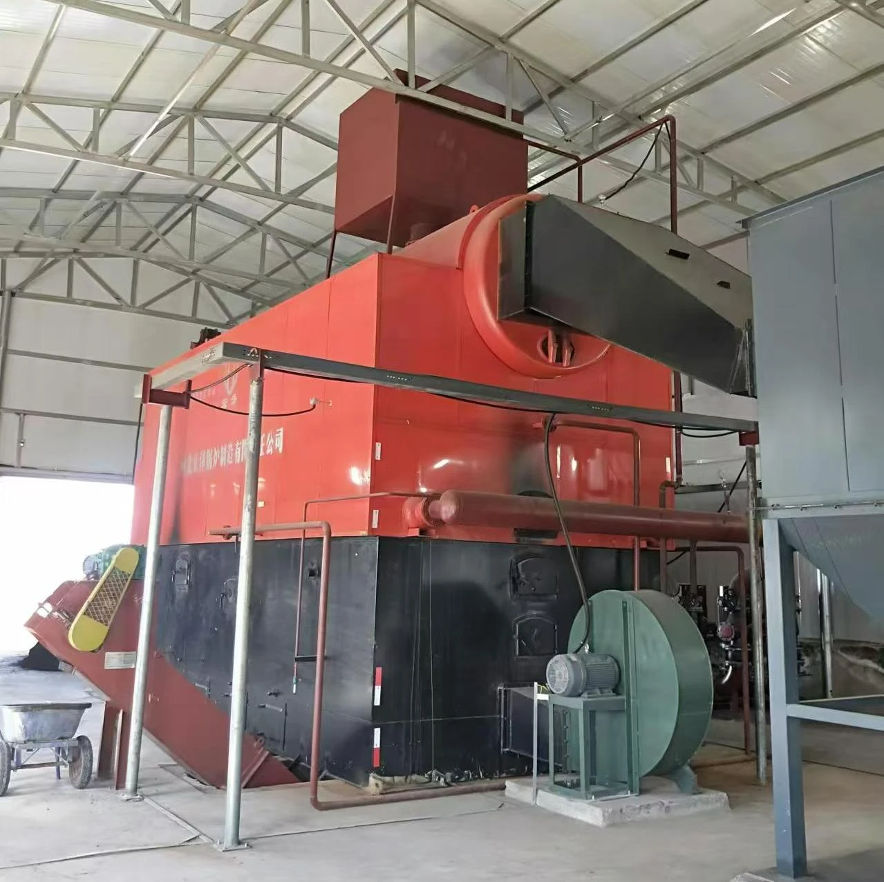
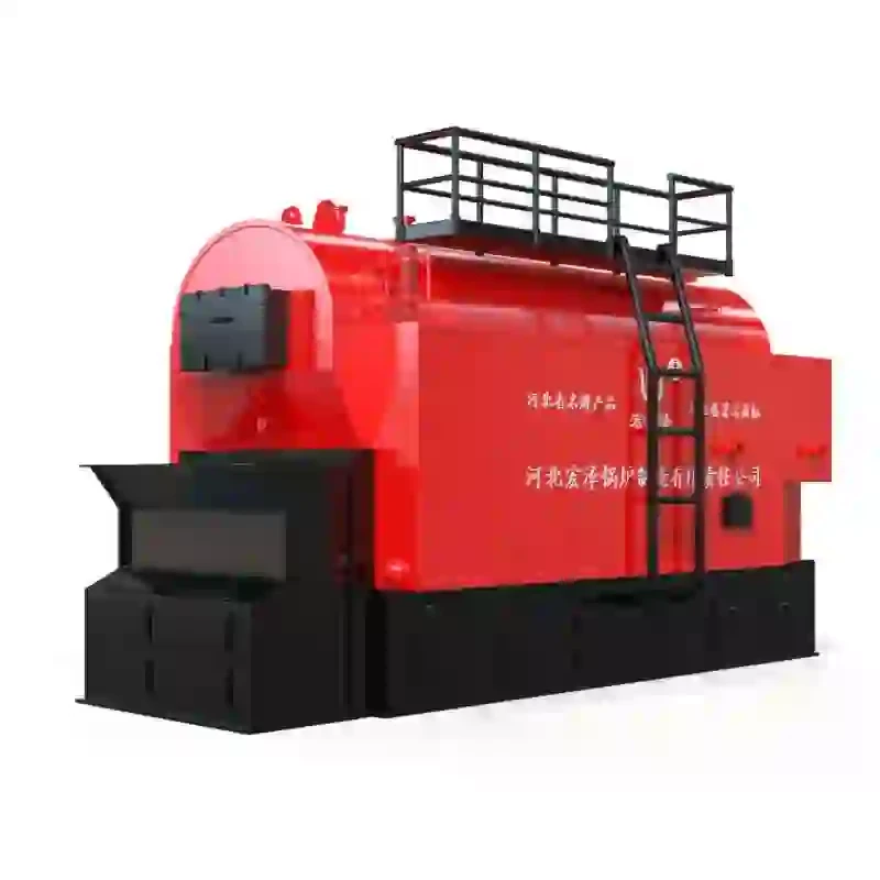
Steam boilers are crucial components in various industrial processes, providing essential thermal energy through steam generation. To grasp how these systems operate, one can refer to steam boiler diagrams, which visually represent the components and flow of operations within the boiler system.
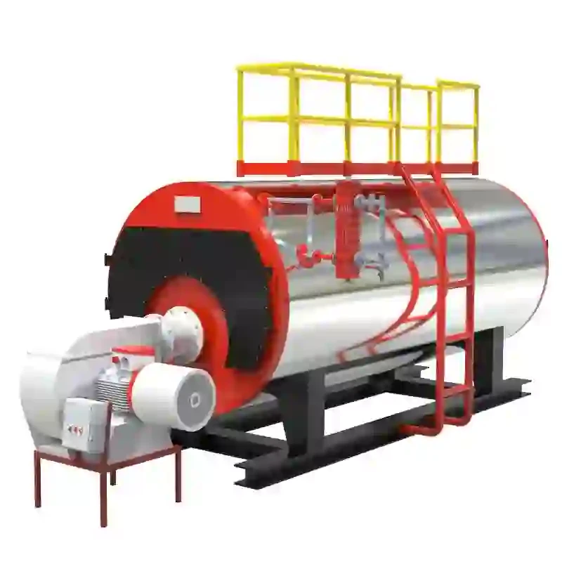
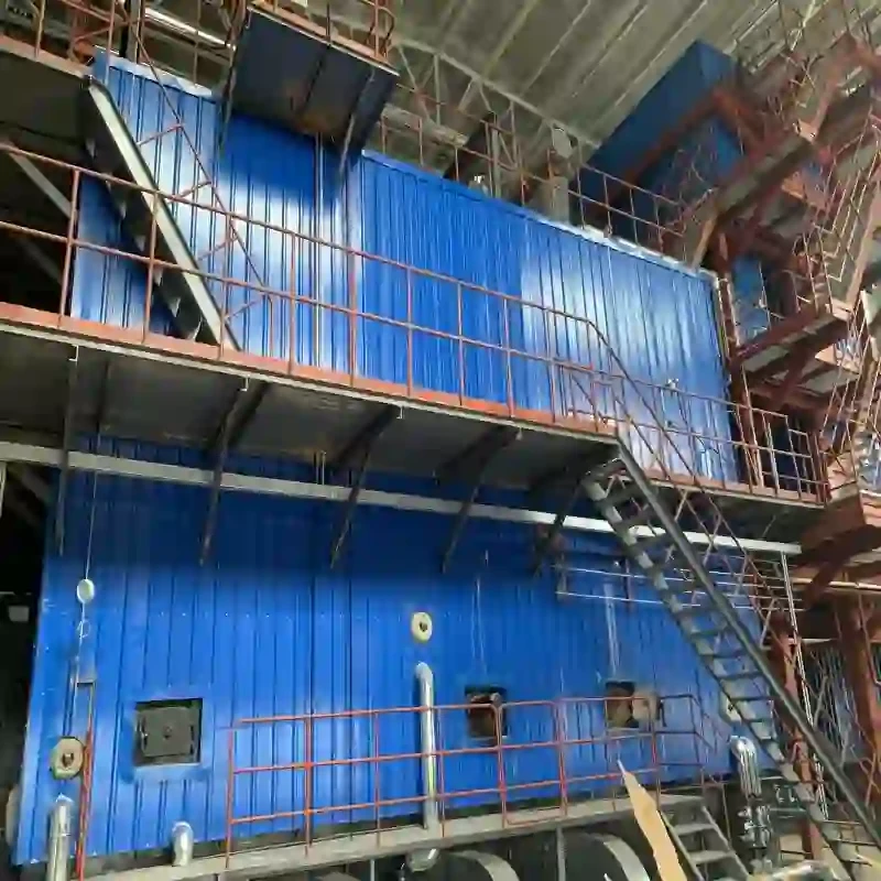
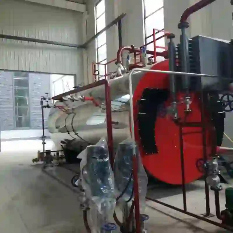
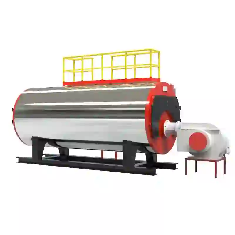
A typical steam boiler diagram includes several key components such as the boiler shell, combustion chamber, heat exchanger, and various valves and controls
. Each of these elements plays a vital role in the efficient functioning of the boiler.Boiler Shell The boiler shell is the outer structure that contains the water and steam. Its design is engineered to withstand high pressure, as steam generation involves heating water to create pressurized steam for energy transfer.
Combustion Chamber Within the boiler shell lies the combustion chamber, where fuel (such as natural gas, oil, or coal) is burned. This process generates heat, which increases the water temperature. The combustion chamber is designed to optimize fuel efficiency and minimize emissions.
Heat Exchanger The heat exchanger transfers energy from the hot gases produced during combustion to the water in the boiler. This is crucial as it ensures that the water reaches its boiling point and converts to steam. Efficiency in this component translates to reduced fuel consumption and lower operational costs.
steam boiler diagram pdf
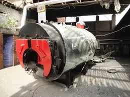
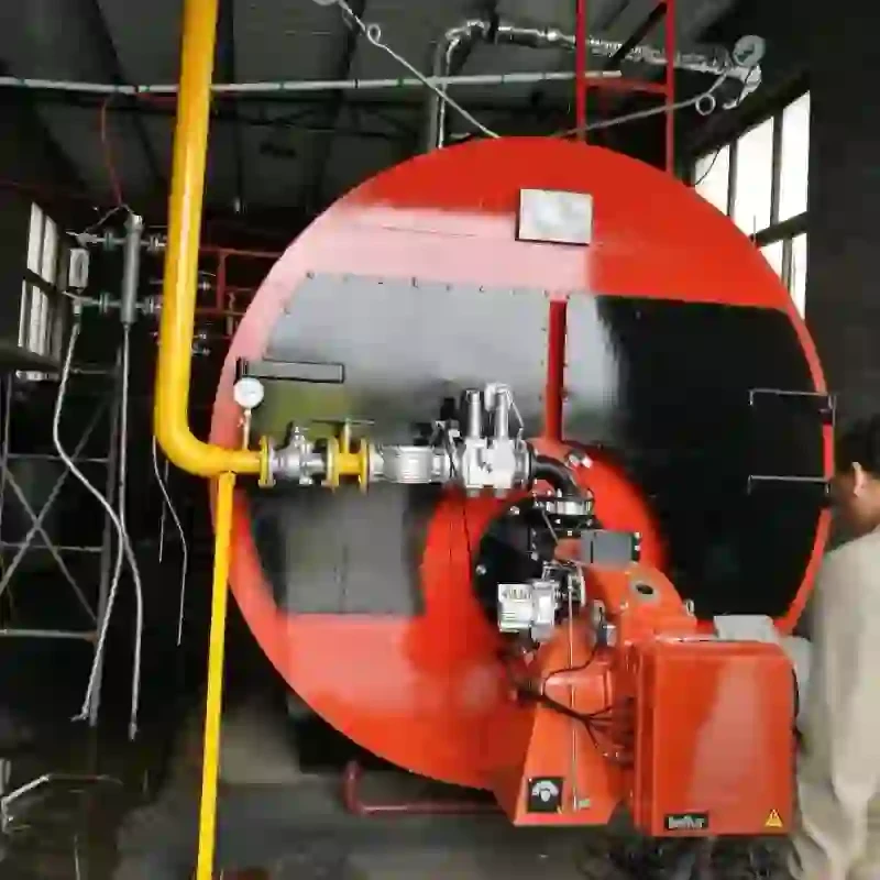
Burner The burner mixes fuel with air to create a combustible mixture. It is equipped with controls to regulate fuel flow and air supply, allowing for efficient and effective combustion. The design of the burner significantly impacts the overall efficiency of the boiler.
Valves and Controls Safety and operational efficiency are maintained through various valves and controls. Safety valves prevent excessive pressure build-up, while control valves regulate the flow of water, steam, and fuel in the system. Additionally, level controls monitor the water level in the boiler, ensuring it does not drop too low, which could lead to overheating.
Piping System The piping system connects the boiler to other components in the facility, allowing steam to be transported where it's needed. This section of the diagram illustrates the routes taken by both steam and condensate (the water formed as steam cools), which is crucial for maintaining system efficiency.
Instruments and Gauges Monitoring is an essential part of steam boiler operation. Instruments and gauges on the diagram display pressure, temperature, and water level, providing operators with real-time data necessary for safe operation.
In conclusion, steam boiler diagrams are invaluable tools for understanding the complex interplay of components involved in steam generation. They not only depict physical locations and connections of various parts but also highlight how these systems work in unison to produce steam efficiently and safely. By studying these diagrams, operators and engineers can optimize boiler performance, enhance safety protocols, and implement maintenance strategies that prolong the life of the boiler, ultimately leading to improved energy efficiency in industrial processes. Understanding these elements allows for better operational practices and encourages best practices within industries reliant on steam generation.
-
High-Efficiency Commercial Oil Fired Steam Boiler for Industry
NewsJul.30,2025
-
High-Efficiency Biomass Fired Thermal Oil Boiler Solutions
NewsJul.30,2025
-
High Efficiency Gas Fired Thermal Oil Boiler for Industrial Heating
NewsJul.29,2025
-
High-Efficiency Gas Fired Hot Water Boiler for Sale – Reliable & Affordable
NewsJul.29,2025
-
High Efficiency Biomass Fired Hot Water Boiler for Industrial and Commercial Use
NewsJul.29,2025
-
High-Efficiency Biomass Fired Hot Water Boiler for Industrial Use
NewsJul.28,2025
Related PRODUCTS


