11월 . 08, 2024 21:46 Back to list
steam boiler schematic diagram
Understanding the Schematic Diagram of a Steam Boiler
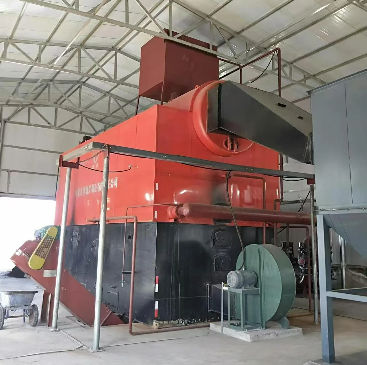
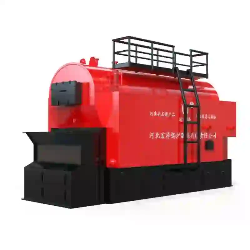
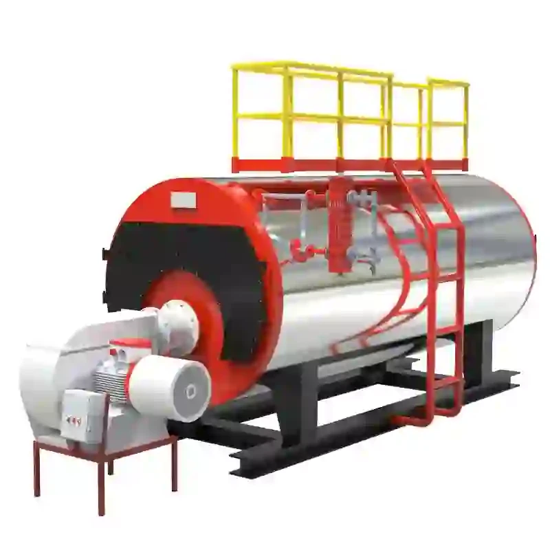
A steam boiler is a crucial component in various industrial applications, providing necessary steam for heating, power generation, and manufacturing processes. The schematic diagram of a steam boiler serves as a vital tool for engineers and technicians, enabling them to understand the system's layout, functionality, and the relationships between its components. In this article, we will delve into the fundamental aspects of a steam boiler schematic diagram, highlighting its components and their roles.
The Components of a Steam Boiler
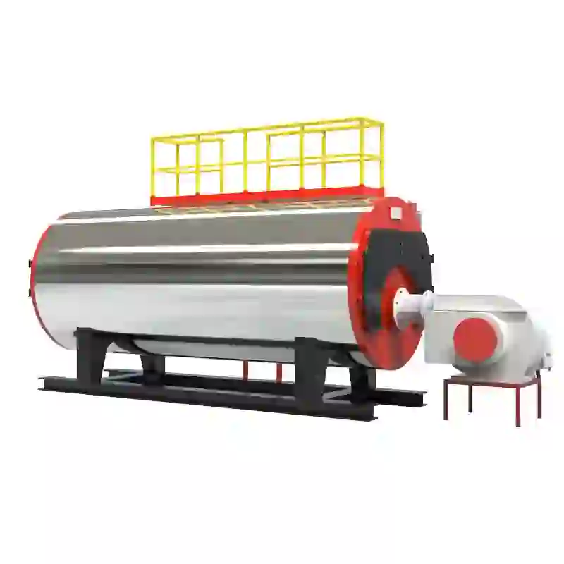
At its core, a steam boiler converts water into steam through the application of heat. The schematic diagram typically illustrates several key components
1. Boiler Shell The boiler shell is the outer casing of the boiler, designed to contain water and steam. It is essential for maintaining pressure and ensuring thermal insulation.
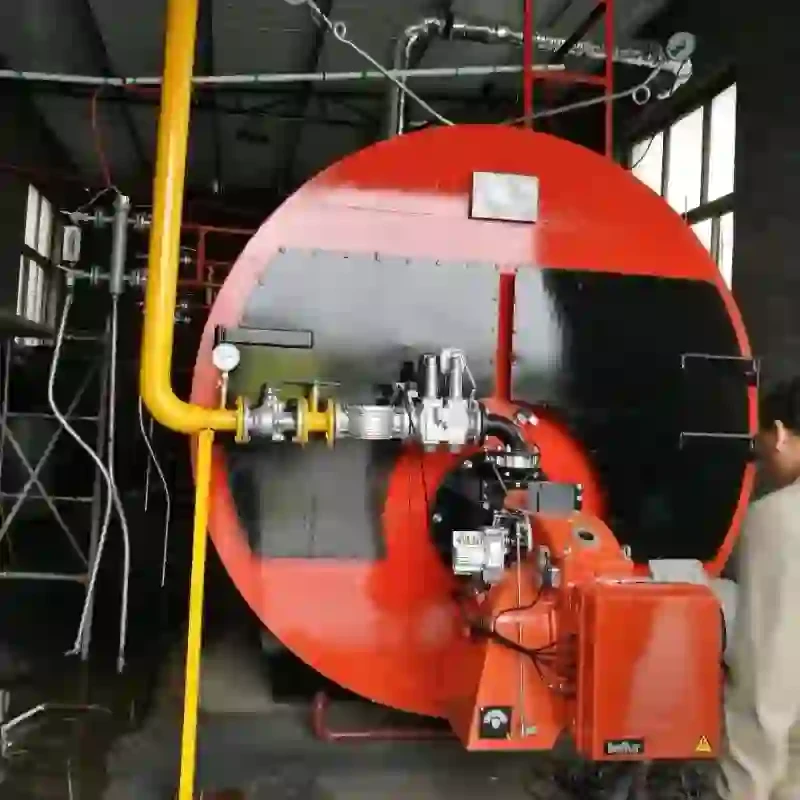
2. Burner This component is responsible for igniting the fuel (which could be natural gas, oil, or coal) to produce heat. The burner is usually located at the base of the boiler and can vary in design based on fuel type.
3. Heat Exchanger The heat exchanger transfers heat from the combustion gases to the water in the boiler. This is a critical part of the efficiency of the boiler, as it maximizes the heat transfer while minimizing energy loss.
4. Water Supply System This system feeds water into the boiler. Return pipes bring water back from the system after steam has been produced, ensuring a continuous cycle. The schematic includes pumps and valves controlling water flow.
5. Steam Outlet Once the water is heated to its boiling point, steam is generated and exits the boiler through the steam outlet. This is often represented in the diagram with a designated line leading into the distribution system.
6. Safety Valves Safety valves are critical for regulating pressure within the boiler. If the pressure exceeds a predetermined limit, the safety valves will open automatically to release steam, preventing potential explosions.
7. Combustion Chamber This is where fuel combustion occurs. The design must ensure efficient burning and complete combustion to maximize heat output and minimize emissions.
steam boiler schematic diagram

8. Condensate Return Line After steam is used, it condenses back into water. The condensate return line directs this water back to the boiler for reuse, improving system efficiency.
Understanding the Schematic
The schematic diagram not only labels these components but also shows how they interconnect. Understanding these relationships is essential for troubleshooting issues and ensuring efficient operation. For instance, if a technician notices that the pressure gauge is showing lower than normal values, they can refer to the schematic to trace back through the system. They may check the water supply system for clogs, inspect the burner for consistent fuel supply, or evaluate the heat exchanger's condition.
Importance of the Schematic Diagram
The schematic diagram is not just a simple representation; it plays several critical roles
- Guidance for Installation It provides a clear reference for installing all components correctly, ensuring safety and efficiency from the start.
- Tool for Maintenance During routine maintenance, technicians use the schematic to identify parts that need inspection or replacement, minimizing downtime.
- Training Resource For new engineers and operators, the schematic serves as an educational tool. It helps them visualize how the boiler functions and the importance of each component in the overall system.
- Problem Diagnosis When issues arise, the schematic diagram allows for quicker diagnostics and repairs. Technicians can systematically isolate problems based on their knowledge of the system layout.
Conclusion
In conclusion, the schematic diagram of a steam boiler is an indispensable resource in understanding and operating these vital systems. It illustrates the complex network of components that work together to produce steam efficiently and safely. By familiarizing oneself with this diagram, engineers and operators can enhance their troubleshooting skills, ensure effective maintenance, and optimize the performance of steam boilers in an array of applications. As industries continue to rely on steam boilers for various operations, a thorough understanding of their schematic diagrams will remain paramount for professionals in the field.
-
Efficient Biomass Fired Hot Water Boiler | AI Heating Solution
NewsAug.01,2025
-
High-Efficiency Gas Thermal Oil Boilers | HPT Models
NewsJul.31,2025
-
Oil Fired Hot Water Boilers Sale - High Efficiency & Affordable
NewsJul.31,2025
-
High-Efficiency Commercial Oil Fired Steam Boiler for Industry
NewsJul.30,2025
-
High-Efficiency Biomass Fired Thermal Oil Boiler Solutions
NewsJul.30,2025
-
High Efficiency Gas Fired Thermal Oil Boiler for Industrial Heating
NewsJul.29,2025
Related PRODUCTS


