ທ.ວ. . 20, 2024 13:55 Back to list
Detailed Schematic Diagram of a Steam Boiler System for Efficient Operation
Understanding Steam Boiler Schematic Diagrams
Steam boilers are integral components in various industrial processes, acting as essential equipment for generating steam that can be used for heating, power generation, or driving machinery. To grasp how these complex systems operate, one must delve into steam boiler schematic diagrams, which provide a visual representation of the boiler's various components and their interconnections.
The Basics of Steam Boilers
A steam boiler operates on a relatively simple principle water is heated to produce steam, which is then utilized for different purposes. The efficiency and safety of this process depend heavily on how well the boiler is designed and how its components work together. The schematic diagram of a steam boiler serves as a blueprint that illustrates the arrangement and functionality of these components.
Key Components in a Schematic Diagram
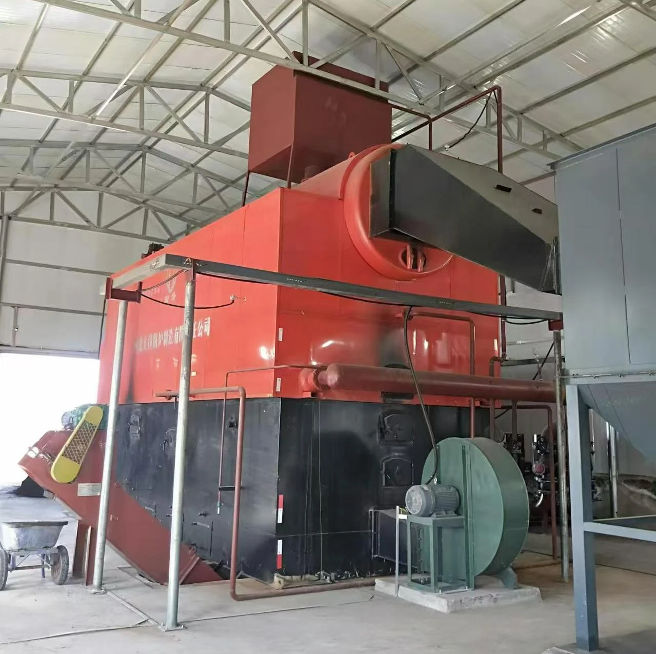
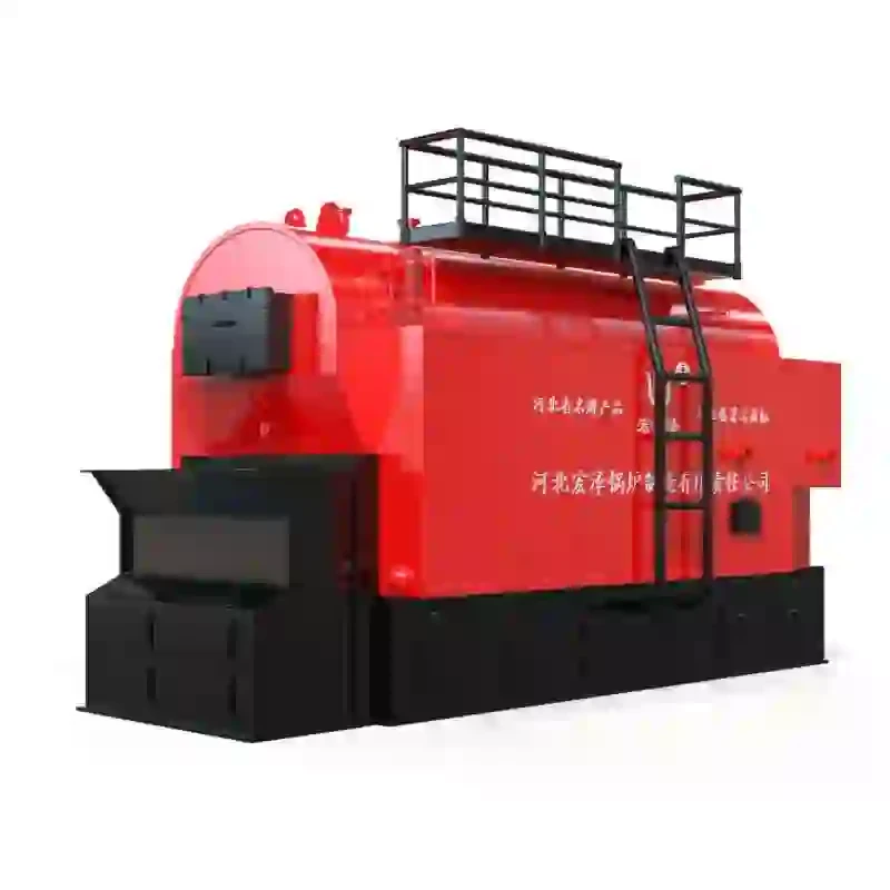
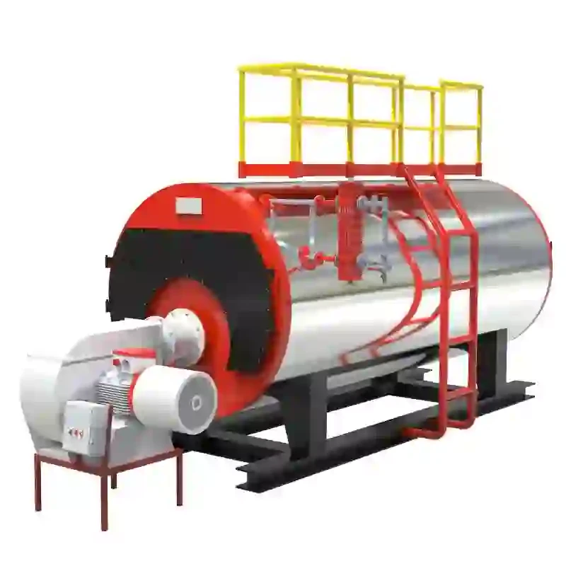
1. Boiler Shell The outer structure of the boiler, it holds the water and steam. The shell is usually made from steel or iron and is designed to withstand high pressures.
2. Water Inlet and Steam Outlet Water enters the boiler through the water inlet, while steam exits through the steam outlet. Properly organizing these flow paths ensures efficient heating and steam generation.
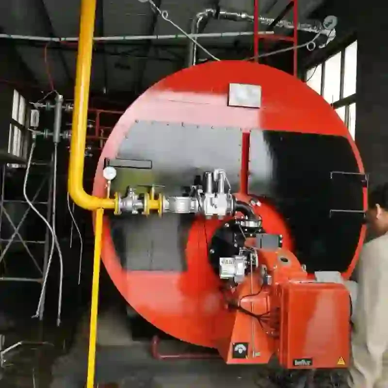
3. Burner The burner is responsible for introducing fuel into the boiler's combustion chamber. In modern systems, this can involve gas, oil, or other fuels. The burner’s design is critical for optimizing fuel efficiency and emissions.
4. Heat Exchanger This component transfers heat from the combustion gases to the water in the boiler. It maximizes heat transfer, improving the overall efficiency of the steam generation process.
5. Safety Valves Safety is paramount in steam boilers. Safety valves protect the system from overpressure scenarios by automatically releasing steam if the pressure exceeds a certain threshold.
steam boiler schematic diagram

6. Control Panel The control panel monitors and regulates the boiler's operation, allowing operators to maintain optimal performance conditions. It typically includes various gauges and sensors to provide real-time feedback on temperature, pressure, and water levels.
Interconnections and Flow Paths
In a steam boiler schematic diagram, all the components are interconnected to form a cohesive system. Arrows and lines typically represent the flow paths for water, steam, and combustion gases. These diagrams help visualize how the various elements interact and are crucial for troubleshooting potential issues.
Water Flow Water is introduced into the boiler from a feedwater tank. It flows through pipes to the heat exchanger, where it is heated by the hot gases produced by the burner. The schematic will often show valves that can isolate different sections for maintenance.
Steam Generation As the water reaches its boiling point, it turns into steam. This process creates pressure within the boiler. The diagram will indicate pressure gauges, showing the current steam pressure levels, which are critical for safe operation.
Combustion Process The combustion chamber houses the burner, where fuel and air mix and ignite. The resulting heat is transferred to the water. The schematic may illustrate the flow of combustion gases, indicating paths to flue gas ducts and the importance of exhaust systems to minimize environmental impact.
Maintenance and Safety
The clarity provided by steam boiler schematic diagrams is not only essential for understanding the function of individual parts but also for routine maintenance and safety checks. Operators can use these diagrams to visualize how the components fit within the larger system, making it easier to perform inspections and identify potential failures.
In conclusion, steam boiler schematic diagrams serve as essential tools for anyone involved in the operation, maintenance, or design of steam boilers. By understanding the various components and their relationships within the system, operators can ensure efficient and safe boiler operation. With the increasing focus on energy efficiency and safety, these diagrams will remain critical resources for industries that rely on steam generation for their processes.
-
Best Steam Boiler Design PDF Free Design Calculation & Diagram Downloads
NewsJun.10,2025
-
Hot Boiler Water Heater Efficient Heating Solutions for Home & Commercial Use
NewsJun.10,2025
-
Steam Boiler Safety Devices High-Quality Protection Valves
NewsJun.10,2025
-
Ultimate Steam Boiler Checklist for Safety & Efficiency
NewsJun.10,2025
-
Optimal Hot Water Boiler Temperature Setting Guide
NewsJun.10,2025
-
Effective Hot Water Boiler Chemical Treatment Protect & Maintain
NewsJun.09,2025
Related PRODUCTS


