11-р сар . 02, 2024 05:38 Back to list
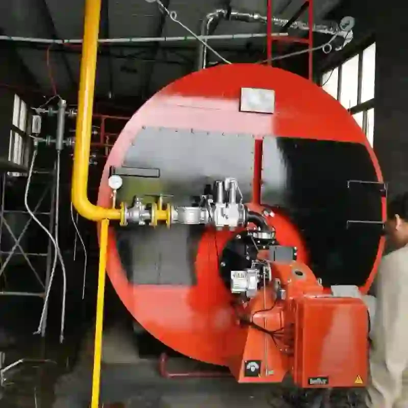
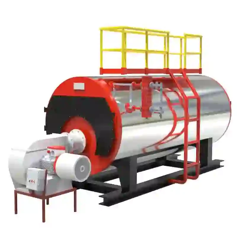
steam boiler electrical diagram
Understanding the Steam Boiler Electrical Diagram
Steam boilers are crucial components in various industrial processes, providing the steam necessary for heating, power generation, and other applications. Understanding the electrical diagram associated with a steam boiler is essential for operators, engineers, and maintenance personnel to ensure safe and efficient operation.
A steam boiler system comprises several key components, including the burner, boiler drum, water feed system, and safety devices. The electrical diagram acts as a roadmap, illustrating how electricity flows through these components, highlighting the interactions and control mechanisms involved.
Electrical Components in the Diagram
1. Control Panel At the heart of the electrical system is the control panel, which houses relays, switches, fuses, and microcontrollers. The control panel receives input from various sensors and provides command signals to different equipment, ensuring that the boiler operates within predefined parameters.
2. Burner Management System (BMS) The BMS is a safety mechanism that monitors the burner operation. It ensures safe ignition, flame monitoring, and emergency shutdown procedures. The electrical diagram shows how various safety interlocks and sensors are wired to the BMS, providing a comprehensive view of system safety.
steam boiler electrical diagram

3. Level Sensors These sensors are critical for monitoring the water level within the boiler. The electrical diagram outlines how the level sensors connect to the control panel, enabling automatic regulation of water feed operations. Maintaining the correct water level is essential to prevent boiler damage or failure.
4. Pressure Sensors Similar to level sensors, pressure sensors play a vital role in boiler operation. They monitor steam pressure and provide feedback to the control system, allowing for appropriate adjustments in fuel supply or heat input. The electrical diagram depicts the interconnections between pressure sensors, the control panel, and the burner.
5. Safety Devices The electrical diagram includes various safety devices, such as pressure relief valves and emergency shutdown systems. These components are designed to prevent overpressure situations and ensure that the boiler can be shut down safely in case of an emergency. The wiring and control circuits for these devices are clearly marked in the diagram, underscoring their importance in boiler safety protocols.
Importance of the Electrical Diagram
The steam boiler electrical diagram is not only a tool for troubleshooting but also serves educational purposes. Understanding the layout and function of each electrical component helps personnel effectively diagnose issues, perform maintenance, and implement necessary repairs quickly. Moreover, adherence to electrical codes and standards is crucial, and the diagram serves as a reference point for compliance.
In conclusion, a detailed examination of the steam boiler electrical diagram reveals the complexities involved in boiler operation. It enhances safety by illustrating how systems interact, while also supporting operational efficiency. For anyone involved with steam boilers, mastering the electrical diagram is an invaluable skill that ultimately contributes to the safe and effective management of these essential systems.
-
Best Steam Boiler Design PDF Free Design Calculation & Diagram Downloads
NewsJun.10,2025
-
Hot Boiler Water Heater Efficient Heating Solutions for Home & Commercial Use
NewsJun.10,2025
-
Steam Boiler Safety Devices High-Quality Protection Valves
NewsJun.10,2025
-
Ultimate Steam Boiler Checklist for Safety & Efficiency
NewsJun.10,2025
-
Optimal Hot Water Boiler Temperature Setting Guide
NewsJun.10,2025
-
Effective Hot Water Boiler Chemical Treatment Protect & Maintain
NewsJun.09,2025
Related PRODUCTS


