अक्ट . 31, 2024 02:50 Back to list
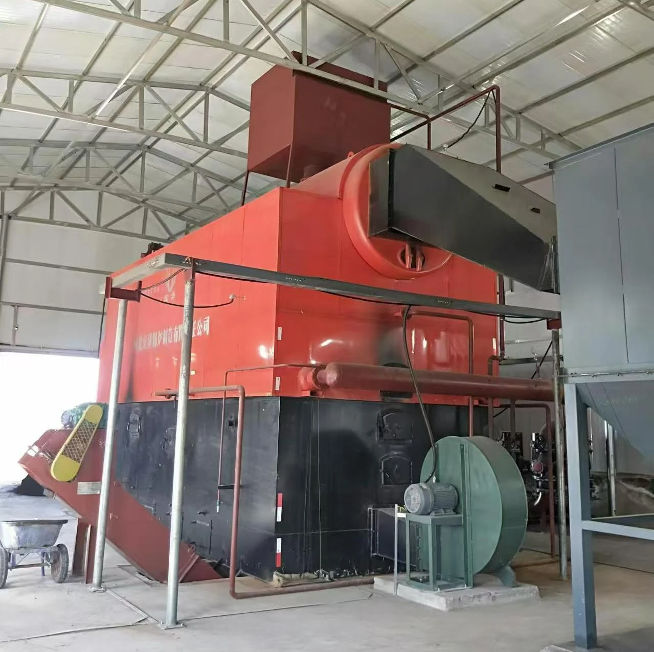
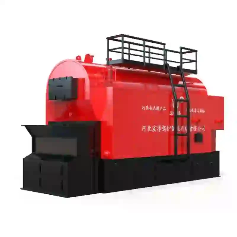
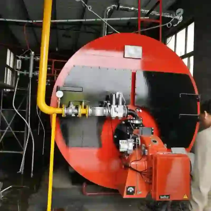
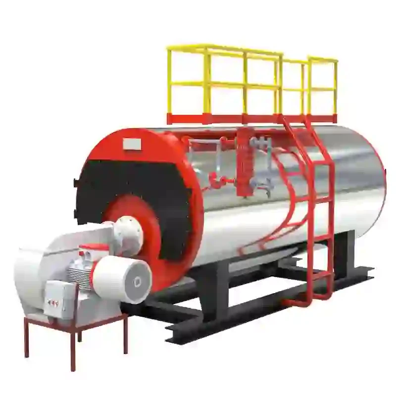
steam boiler system schematic diagram
Understanding the Steam Boiler System A Schematic Overview
A steam boiler system is an essential component in various industrial applications, ranging from power generation to manufacturing processes. Understanding the schematic diagram of a steam boiler system is crucial for engineers, technicians, and operators to ensure efficient operation and maintenance.
At its core, a steam boiler converts water into steam through the application of heat
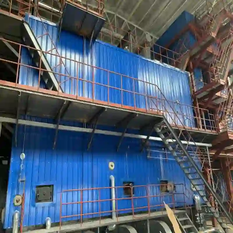
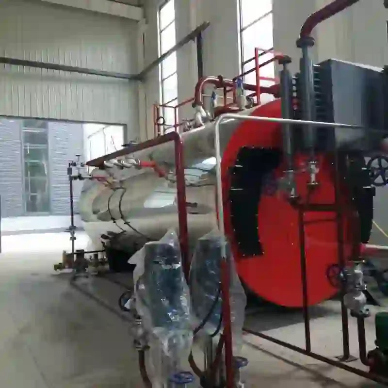
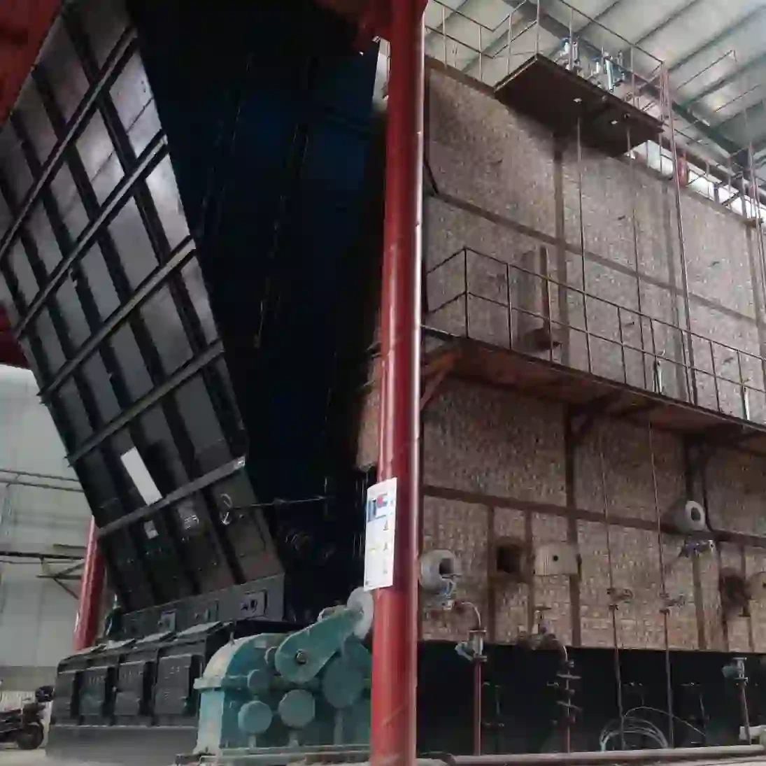
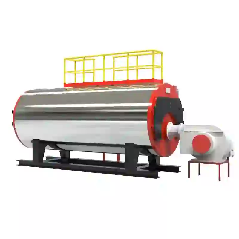
. The schematic diagram typically illustrates the main components involved in this process, including the boiler itself, feedwater system, fuel supply, steam drum, and various control equipment.The feedwater system is the first component in the schematic, responsible for supplying water to the boiler. This system may include a feedwater pump that pressurizes water from a storage tank, ensuring a steady flow into the boiler. Proper treatment of feedwater is vital to prevent scale buildup and corrosion inside the boiler, which could lead to operational inefficiencies or failures.
Next, the fuel supply system, which may utilize natural gas, oil, or coal, delivers the fuel to the combustion chamber where it is ignited. The diagram often shows a burner assembly that mixes fuel with air for efficient combustion. The combustion process generates heat, which is transferred to the boiler water, transforming it into steam.
steam boiler system schematic diagram

The steam produced in the boiler rises to the steam drum, where it is separated from any residual water. Here, the schematic highlights the importance of maintaining proper pressure and temperature levels, as these factors directly impact the system's efficiency and safety.
A series of safety valves and pressure gauges is illustrated in the schematic to ensure that the boiler operates within the designated parameters. Safety valves prevent excessive pressure buildup, while gauges provide real-time monitoring of temperature and pressure, allowing operators to make informed decisions.
In addition, the schematic may indicate various control systems, including automated controls that adjust fuel and water flow rates based on demand. These controls optimize performance, reduce fuel consumption, and minimize emissions, contributing to environmentally friendly operations.
Finally, the diagram often shows the steam distribution network, connecting the boiler to end-user applications such as turbines, heat exchangers, or process equipment. This network is crucial for delivering the steam where it is needed most, ensuring that the overall system operates efficiently.
In conclusion, the schematic diagram of a steam boiler system provides a comprehensive overview of its components and functioning. Mastery of this diagram not only equips professionals with the knowledge to operate and maintain these systems but also fosters improvements in safety, efficiency, and environmental performance. Understanding the interplay of each element within the schematic is key to harnessing the power of steam technology effectively.
-
High-Efficiency Commercial Oil Fired Steam Boiler for Industry
NewsJul.30,2025
-
High-Efficiency Biomass Fired Thermal Oil Boiler Solutions
NewsJul.30,2025
-
High Efficiency Gas Fired Thermal Oil Boiler for Industrial Heating
NewsJul.29,2025
-
High-Efficiency Gas Fired Hot Water Boiler for Sale – Reliable & Affordable
NewsJul.29,2025
-
High Efficiency Biomass Fired Hot Water Boiler for Industrial and Commercial Use
NewsJul.29,2025
-
High-Efficiency Biomass Fired Hot Water Boiler for Industrial Use
NewsJul.28,2025
Related PRODUCTS


