Aug . 30, 2024 21:03 Back to list
steam boiler system schematic diagram
Understanding the Steam Boiler System Schematic Diagram
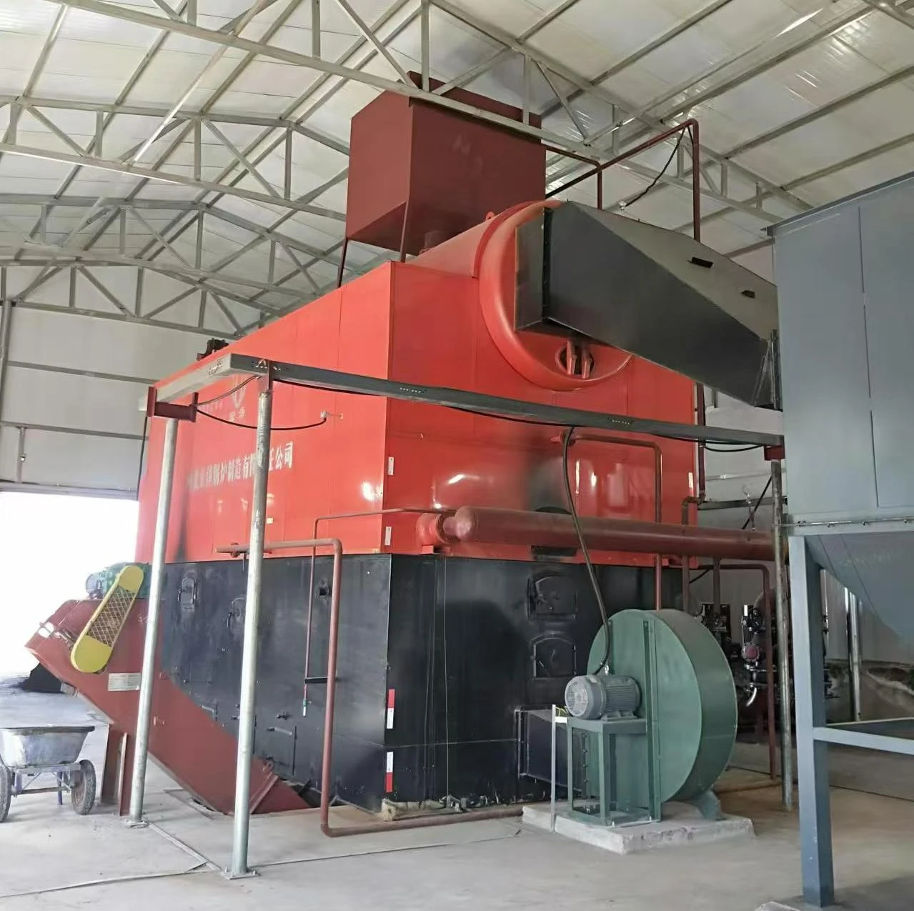
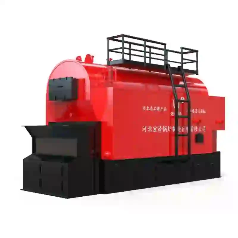
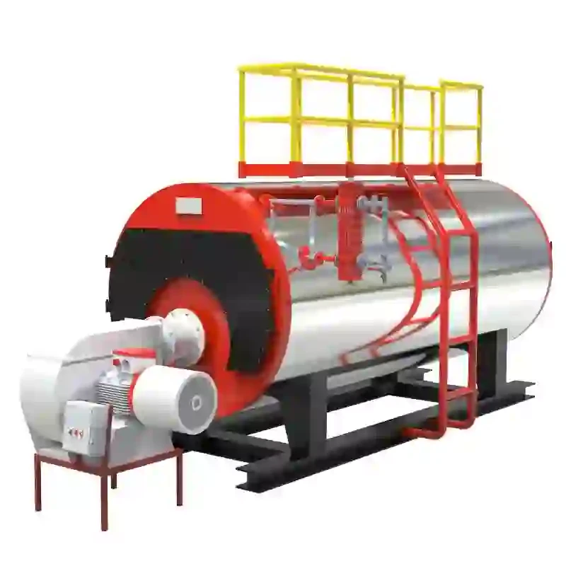
A steam boiler system schematic diagram is an essential tool for both understanding and engineering steam-based heating systems. This diagram provides a visual representation of the components and their interconnections within the boiler system, helping technicians, engineers, and operators to grasp how the system functions and to diagnose potential issues.
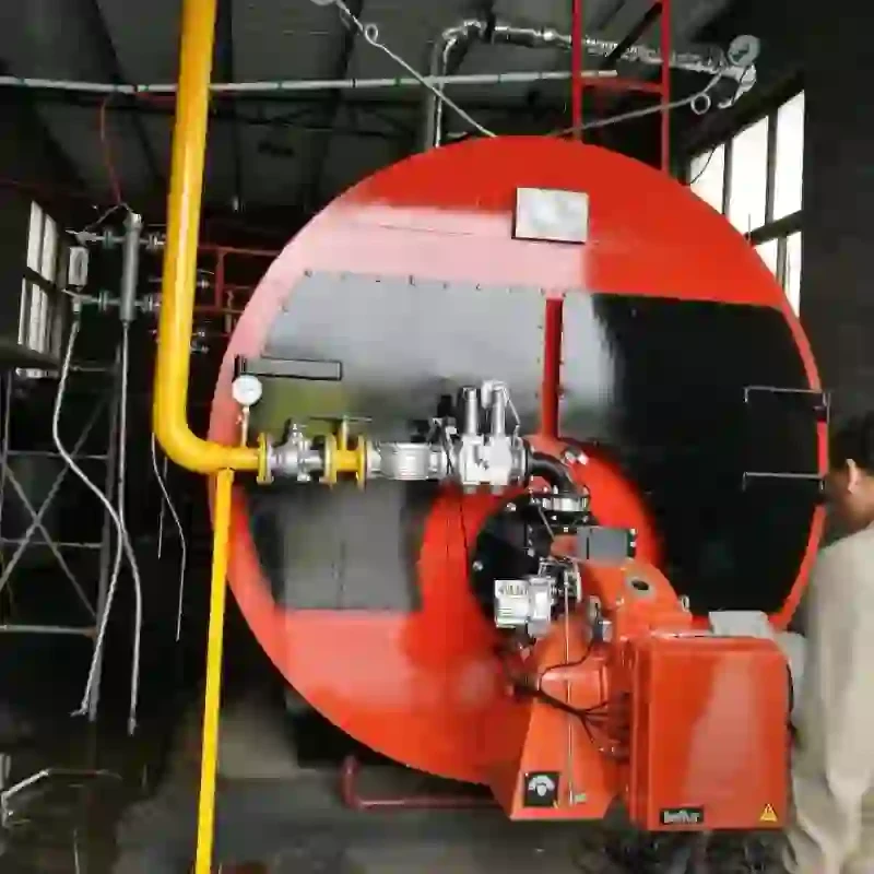
At the heart of the steam boiler system is the boiler itself, which converts water into steam through the application of heat. This heating process typically comes from burning fuel sources, such as natural gas, oil, or coal, or through electrical heating elements. The schematic diagram starts with the fuel supply line, which leads to the burner assembly. The burner ignites the fuel and generates heat, which is then transferred to the heat exchanger inside the boiler.
One of the crucial elements depicted in the schematic is the water feed system, which supplies water to the boiler for conversion into steam. This is usually controlled by a feed water pump that ensures the boiler has sufficient water levels to operate efficiently. The schematic will also highlight various safety measures such as pressure relief valves and water level controls, which are critical for preventing over-pressurization and ensuring safe operation of the boiler.
steam boiler system schematic diagram

As steam is generated, it travels through piping systems to its point of use. The schematic often includes details about the steam pipes, including insulation, valves for flow regulation, and pressure gauges that monitor the steam pressure throughout the system. Understanding these components is vital for maintaining optimal performance and safety.
Moreover, the schematic may feature ancillary components like condensate return systems that collect and recycle unused steam, allowing for energy efficiency. The condensate is often returned to the boiler as feed water, minimizing water and energy waste.
In addition to depicting physical components, a steam boiler system schematic diagram often includes operational flow directions, which help technicians identify how steam moves through the system. This is crucial for troubleshooting purposes, as it guides operators in pinpointing malfunctioning areas that may cause inefficiencies or outages.
In conclusion, a steam boiler system schematic diagram serves as a comprehensive blueprint of the system's operation and design. By understanding this diagram, professionals in the field can ensure that steam boiler systems operate safely and efficiently, ultimately providing the necessary heat for a variety of industrial and commercial applications. Through careful analysis of the schematic, informed decisions can be made regarding maintenance, upgrades, and troubleshooting, contributing to the longevity and reliability of steam boiler systems.
-
High-Efficiency Commercial Oil Fired Steam Boiler for Industry
NewsJul.30,2025
-
High-Efficiency Biomass Fired Thermal Oil Boiler Solutions
NewsJul.30,2025
-
High Efficiency Gas Fired Thermal Oil Boiler for Industrial Heating
NewsJul.29,2025
-
High-Efficiency Gas Fired Hot Water Boiler for Sale – Reliable & Affordable
NewsJul.29,2025
-
High Efficiency Biomass Fired Hot Water Boiler for Industrial and Commercial Use
NewsJul.29,2025
-
High-Efficiency Biomass Fired Hot Water Boiler for Industrial Use
NewsJul.28,2025
Related PRODUCTS


