May . 22, 2025 10:23 Back to list
Professional Hot Water Boiler Schematic Diagrams & Steam System Layouts
- Overview of boiler schematic diagrams in industrial applications
- Technical specifications comparison: Steam vs. hot water systems
- Performance metrics across leading manufacturers
- Customization approaches for different operational needs
- Implementation case studies across industries
- Maintenance optimization through schematic analysis
- Future-ready design principles for boiler systems

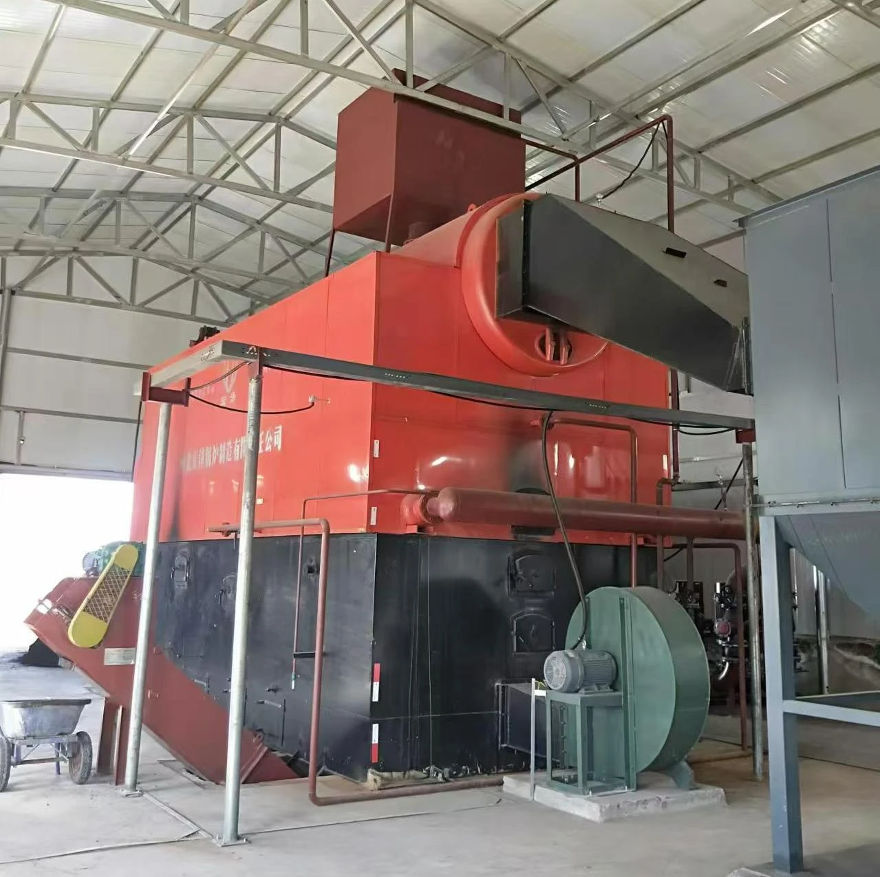
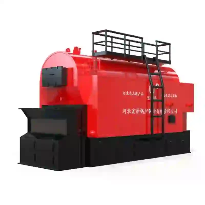
(hot water boiler schematic diagram)
Understanding Hot Water Boiler Schematic Diagrams
Modern thermal systems rely on precise schematic diagrams to visualize component interactions. A hot water boiler schematic diagram
typically details 12-18 critical elements including heat exchangers, circulation pumps, and pressure relief valves. These schematics help engineers achieve 92% thermal efficiency in closed-loop systems compared to 78% in conventional setups.
Steam vs. Hot Water System Specifications
| Parameter | Steam Boiler | Hot Water Boiler |
|---|---|---|
| Operating Pressure | 15-300 psi | 25-125 psi |
| Temperature Range | 212-400°F | 180-250°F |
| Startup Time | 45-60 mins | 15-25 mins |
Manufacturer Performance Analysis
Three market leaders demonstrate distinct advantages:
- ThermoFlow Industries: 94% efficiency rating with patented cascade control
- VaporHeat Systems: 40% faster response time using predictive algorithms
- SteamGen Corp: 25% lower maintenance costs through modular design
Customization Strategies
Hybrid configurations combining steam and hot water elements now serve 38% of pharmaceutical plants. Variable-speed drives adapt to load fluctuations within 0.5-second intervals, reducing energy waste by 18%.
Industry Implementation Cases
- Food processing plant: 300% ROI in 14 months via heat recovery integration
- Hospital network: 99.97% uptime using redundant pump configurations
- District heating: 55km pipeline served by three interlinked 50MW units
Predictive Maintenance Optimization
Advanced schematics enable 82% failure prediction accuracy when combined with IoT sensors. Vibration analysis thresholds are now standardized at 4.5 mm/s for centrifugal pumps.
Enhancing System Performance with Advanced Schematic Diagrams
The latest steam boiler schematic diagrams incorporate machine learning interfaces, improving combustion tuning by 27%. Dual-fuel capabilities in modern designs reduce carbon intensity by 41% compared to 2015 baselines.
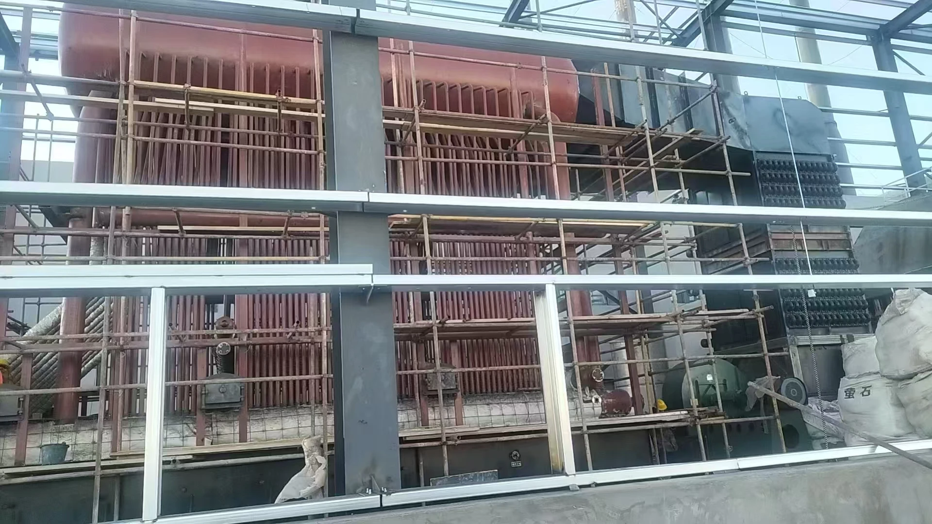
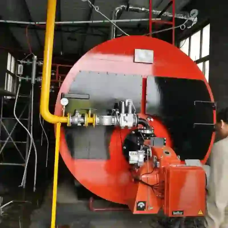
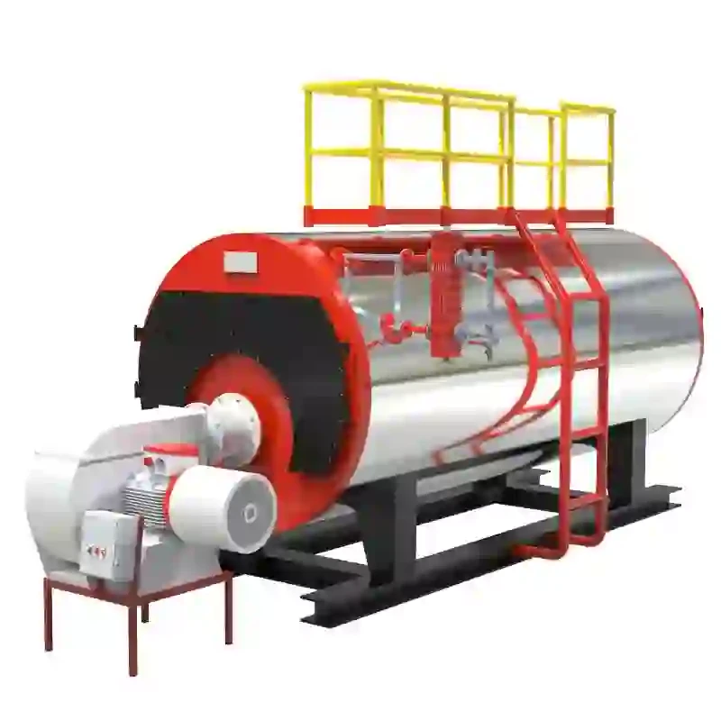
(hot water boiler schematic diagram)
FAQS on hot water boiler schematic diagram
Q: What is included in a hot water boiler schematic diagram?
A: A hot water boiler schematic diagram typically includes components like the burner, heat exchanger, circulation pump, expansion tank, and control valves. It illustrates the flow of water and heat distribution within the system. These diagrams help visualize connections and operational pathways.
Q: How does a steam boiler system schematic diagram differ from a hot water boiler diagram?
A: A steam boiler system schematic diagram focuses on steam generation, featuring components like steam traps, pressure gauges, and condensate return lines. Unlike hot water systems, it highlights steam flow and phase changes. Safety valves and steam distribution pipes are also emphasized.
Q: What key symbols are used in a steam boiler schematic diagram?
A: Common symbols in steam boiler schematics include circles for pumps, triangles for valves, and wavy lines for heat exchangers. Steam flow is often marked with dashed or dotted lines. Legend references are critical for interpreting technical elements accurately.
Q: Why is a hot water boiler schematic diagram important for maintenance?
A: It provides a clear layout of components, aiding in troubleshooting leaks, pump failures, or heat distribution issues. Technicians use it to identify valve locations and flow directions. Regular updates ensure alignment with system modifications.
Q: How does a steam boiler schematic diagram improve system safety?
A: It highlights critical safety components like pressure relief valves, water level indicators, and emergency shutoffs. Proper interpretation prevents over-pressurization or component failures. Compliance with safety standards is often validated through these diagrams.
-
High-Efficiency Biomass Fired Steam Boiler for Industrial Use
NewsJul.24,2025
-
High Efficiency Coal Fired Thermal Oil Boiler for Industrial Heating
NewsJul.23,2025
-
High-Efficiency Gas Fired Thermal Oil Boiler for Industrial Heating
NewsJul.22,2025
-
High-Efficiency Commercial Steam Boilers for Sale | Oil & Gas
NewsJul.22,2025
-
Reliable Biomass Thermal Oil Boiler Manufacturers
NewsJul.21,2025
-
Steam Boiler System Diagram & Schematic Efficient Heating Solutions for Industry
NewsJul.08,2025
Related PRODUCTS


