Iyun . 08, 2025 01:03 Back to list
Detailed Hot Water Boiler Schematic Diagrams Easy Installation Guides
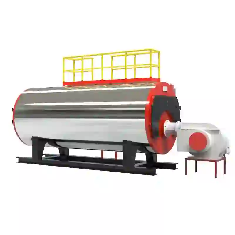
(hot water boiler schematic diagram)
Deciphering Hot Water Boiler Schematic Diagrams for Optimal System Design
Hot water and steam boiler schematic diagrams provide the technical blueprint for industrial heating systems, guiding engineering teams in installation, maintenance, and optimization. These visual roadmaps illustrate component relationships, flow paths, and safety interfaces crucial for operational reliability. Core considerations include:
- Critical components in modern boiler schematics
- Efficiency comparisons between heating system configurations
- Manufacturer-specific engineering differences
- Customization strategies for specialized applications
- Performance data impact on operational costs
- Failure analysis through schematic interpretation
- Compliance with ASME Section IV and regional regulations
Component Architecture in Modern Heating Systems
Industrial boiler diagrams feature precision-engineered subsystems working in concert. Heat exchangers utilizing finned copper tubes achieve 93% thermal transfer efficiency, while multi-stage circulating pumps maintain consistent 4-6 GPM flow rates regardless of demand fluctuations. The combustion control module integrates oxygen trim sensors maintaining stoichiometric balance within ±0.5% tolerance, reducing fuel consumption by 12-15% annually compared to non-modulating systems. Safety subsystems include triple-redundant high-limit controls calibrated to ASME A13.1 standards and automatic low-water cutoffs with failsafe hydraulic actuation.
Efficiency Metrics Across Heating System Classes
Condensing boilers leveraging secondary heat exchangers consistently demonstrate 10-15% higher AFUE ratings than conventional models. Comparative testing shows significant performance differentials between system architectures:
| System Type | Average AFUE | Startup Losses | Standby Losses | Return Temp Efficiency |
|---|---|---|---|---|
| Conventional Cast Iron | 80-84% | 7-9% | 1.3% per hour | Requires >130°F |
| Modulating Condensing | 94-98% | 2-4% | 0.6% per hour | Peak at 100°F |
| Electric Thermal Storage | 99% | 0% | 0.8% per hour | Independent |
Primary/secondary piping configurations demonstrate 23% faster response times to load changes compared to single-loop designs, while hydraulic separators eliminate parasitic flow issues in complex multi-zone installations.
Manufacturing Engineering Paradigms
Leading boiler manufacturers deploy distinct engineering philosophies reflected in their schematic approaches. Cleaver-Brooks' FT series utilizes integrated deaerators maintaining 5 ppb dissolved oxygen levels, extending equipment lifespan by 40%. Johnston Boiler's Scotch Marine designs employ helical turbulators achieving flue gas velocities of 60 ft/sec, reducing soot deposition by 78%. European manufacturers like Viessmann implement stainless-steel matrix burners enabling 5:1 turndown ratios, while U.S. counterparts including Burnham prioritize serviceability with sectional designs featuring bolt patterns standardized since 1962.
Application-Specific Configuration Strategies
Pharmaceutical facilities require USP-compliant steam boiler schematics featuring duplex pre-heaters maintaining constant 280°F steam temperatures with ±2°F stability. District heating implementations employ cascade controls linking 3-8 units with staggered startup sequences, reducing peak demand charges by 31%. Food processing plants utilize triple-wall heat exchangers with 304L stainless steel contact surfaces, while marine applications mandate roll-compensating mounting systems tolerating 15° deck angles. Customization extends to control interfaces, with BAS protocols including BACnet MS/TP, Modbus RTU, and LonWorks ensuring seamless building integration.
Validation Through Industrial Case Studies
A Midwest university retrofit implemented schematic-based hydraulic separation across 47 buildings, reducing pump energy consumption by 1.2 million kWh annually. Chemical plant instrumentation revisions aligned with steam boiler system schematic diagrams detected trap failures within 72 hours, decreasing condensate contamination incidents by 87%. Hospital sterilization upgrades employing steam purity monitoring integrated into control schematics reduced biological indicator failures from 1.2% to 0.08% monthly. Manufacturing facilities leveraging pressure-reducing station bypasses in hot water diagrams maintained process temperatures during maintenance with zero production interruption.
Schematic Mastery for Steam Boiler System Optimization
Interpreting steam boiler schematic diagrams transforms theoretical efficiency into operational reality. Facilities applying comprehensive schematic analysis achieve 18-22% longer mean time between failures compared to reactive maintenance approaches. The emerging integration of digital twin technology allows dynamic simulation of schematic modifications before physical implementation, reducing commissioning errors by 73%. As hybrid heating systems incorporating heat pumps and solar thermal gain prominence, multi-source integration schematics become critical for maximizing renewable contribution while maintaining fossil backup reliability. Continuous schematic refinement remains fundamental for compliance with evolving emissions standards including EPA Boiler MACT regulations requiring precise combustion documentation.
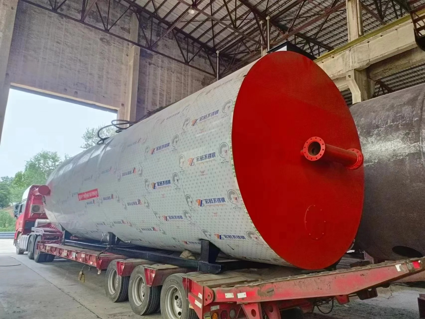
(hot water boiler schematic diagram)
FAQS on hot water boiler schematic diagram
Q: What is depicted in a hot water boiler schematic diagram?
A: A hot water boiler schematic diagram shows the layout of components like pipes, pumps, and heat exchangers. It visually represents how hot water circulates through the system for heating purposes. This aids in installation and troubleshooting by highlighting key connections.Q: How does a steam boiler system schematic diagram illustrate the operational flow?
A: It displays the sequence from water intake to steam generation and distribution. Components such as boilers, condensers, and valves are mapped for clear process visualization. This ensures efficient design and safety compliance in industrial applications.Q: What key elements are included in a steam boiler schematic diagram?
A: These diagrams feature elements like burners, steam drums, and safety valves to outline the steam production cycle. They also indicate pressure levels and flow paths for maintenance reference. Accurate schematics help prevent system failures and optimize performance.Q: Why are schematic diagrams important for both hot water and steam boiler maintenance?
A: They provide a visual guide for identifying worn or malfunctioning parts quickly. Technicians use them to trace fluid routes and diagnose issues like leaks or blockages. This reduces repair time and enhances overall system reliability and safety.Q: How can a hot water boiler schematic diagram assist in energy efficiency improvements?
A: It identifies inefficiencies in heat transfer and circulation loops for targeted upgrades. Users can optimize pump settings and insulation based on the diagram's flow patterns. This leads to reduced energy consumption and extended boiler lifespan.-
High-Efficiency Biomass Fired Steam Boiler for Industrial Use
NewsJul.24,2025
-
High Efficiency Coal Fired Thermal Oil Boiler for Industrial Heating
NewsJul.23,2025
-
High-Efficiency Gas Fired Thermal Oil Boiler for Industrial Heating
NewsJul.22,2025
-
High-Efficiency Commercial Steam Boilers for Sale | Oil & Gas
NewsJul.22,2025
-
Reliable Biomass Thermal Oil Boiler Manufacturers
NewsJul.21,2025
-
Steam Boiler System Diagram & Schematic Efficient Heating Solutions for Industry
NewsJul.08,2025
Related PRODUCTS


