Sen . 07, 2024 23:43 Back to list
steam boiler schematic
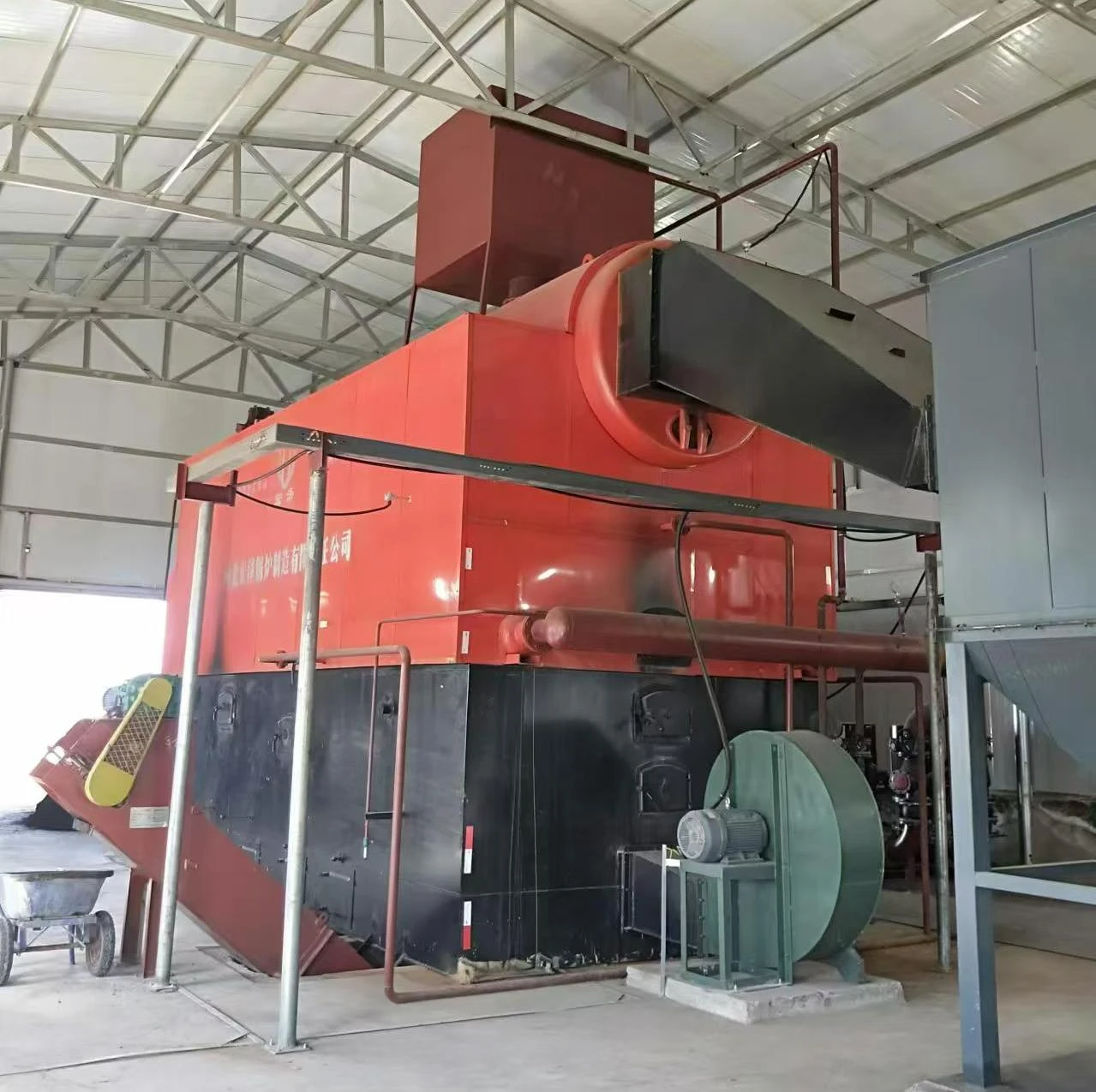
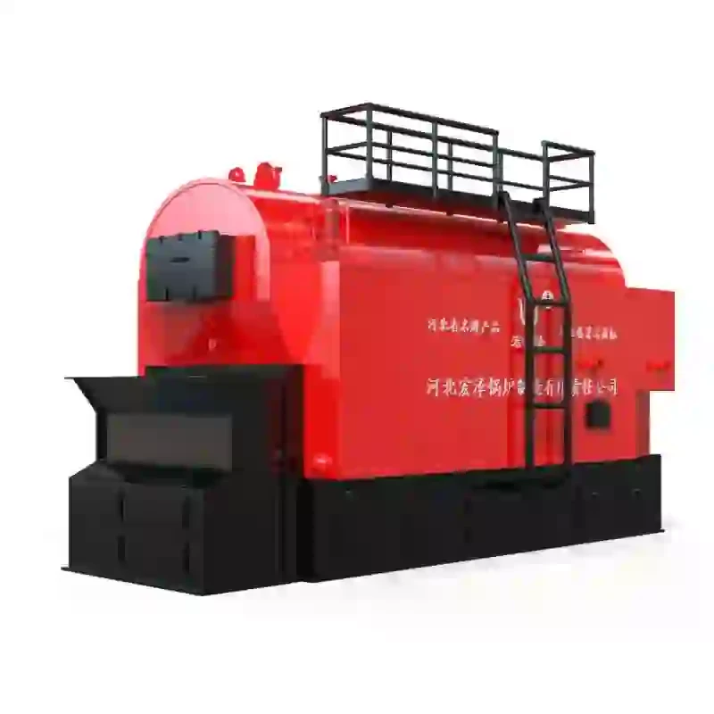
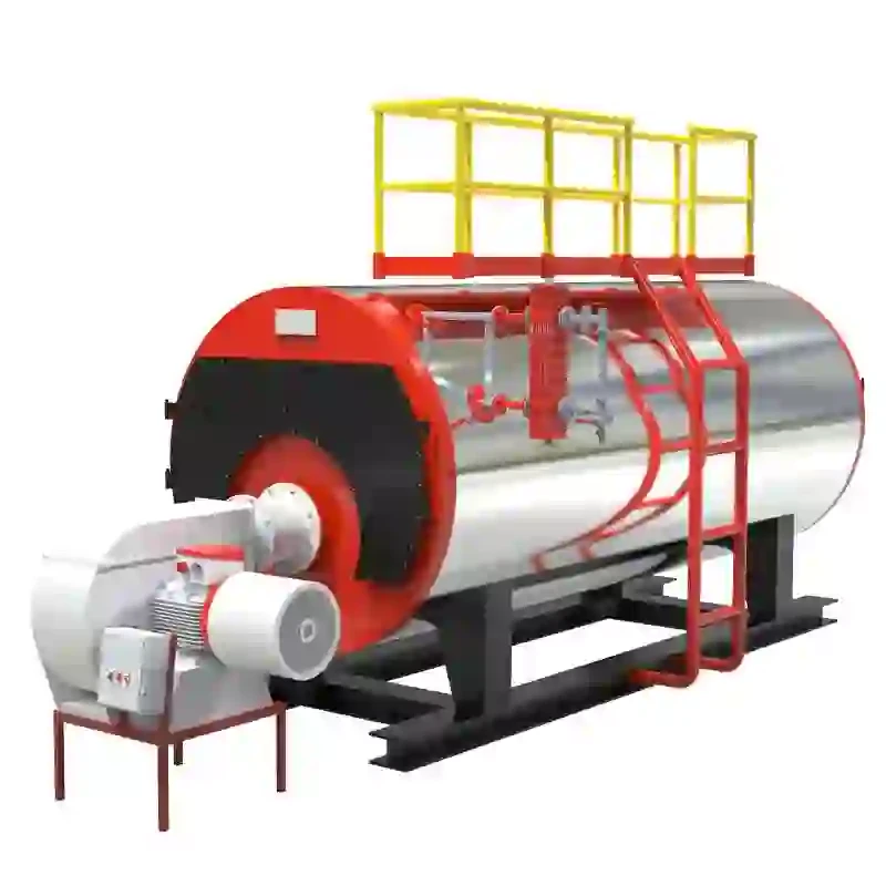
Understanding the Schematic of a Steam Boiler
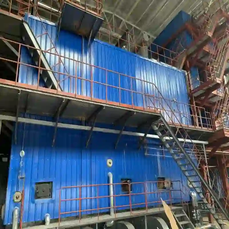
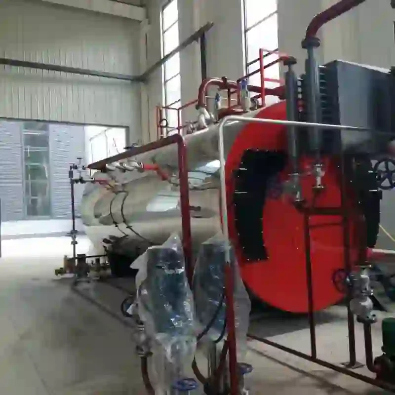
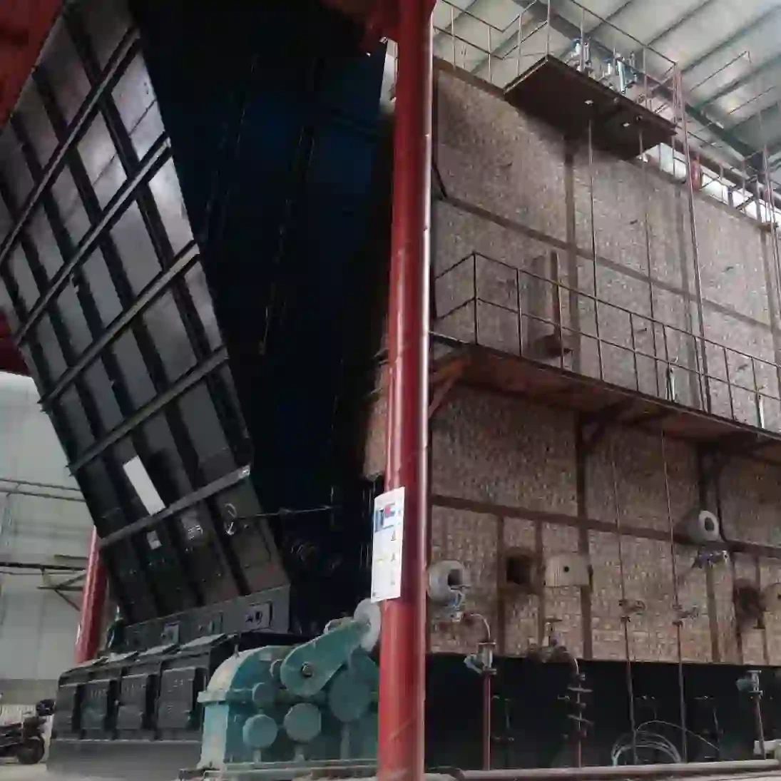
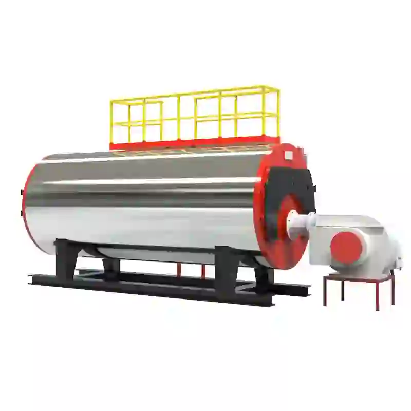
A steam boiler is a vital component in various industrial processes, providing the necessary steam for heating, power generation, and other applications. Understanding the schematic of a steam boiler is crucial for engineers, technicians, and operators working with steam systems. This article will break down the key components and functions illustrated in a typical steam boiler schematic.
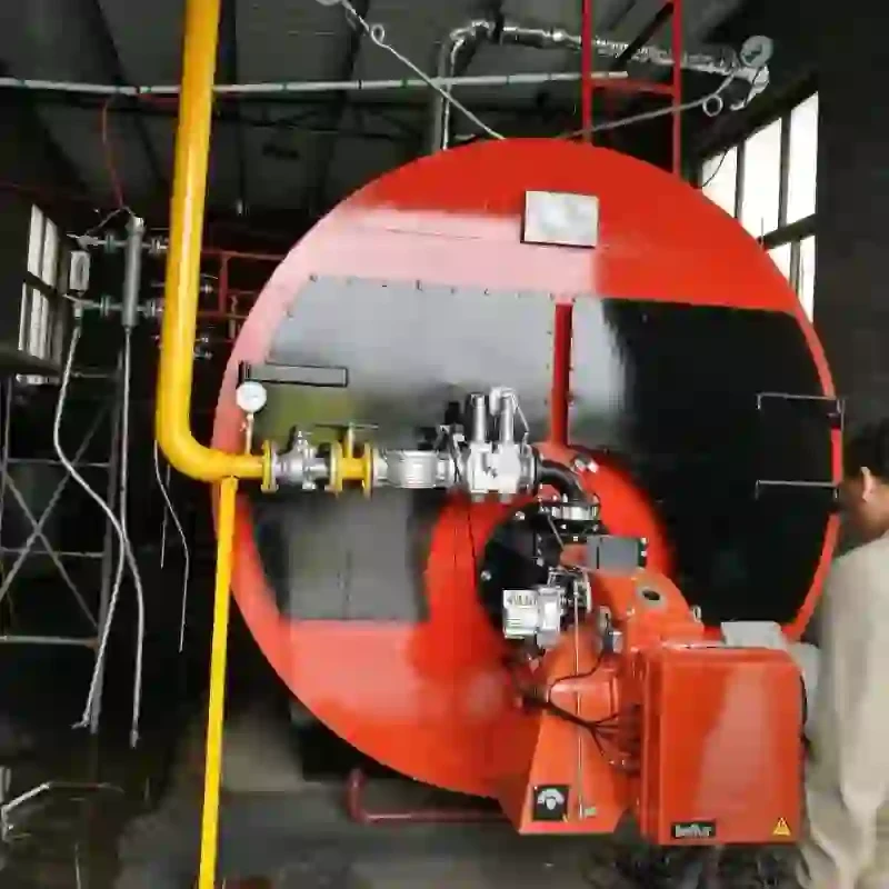
At the core of the steam boiler is the burner. The burner is responsible for introducing fuel and air into the combustion chamber where they ignite to produce heat. This heat is then used to raise the temperature of water in the boiler. The schematic will often depict the burner in relation to the combustion chamber, which houses the flames and is designed to optimize the combustion process for maximum efficiency and safety.
Next in the schematic is the water supply system. This system includes pipes, valves, and pumps that feed water into the boiler. Typically, the schematic will show a feedwater line leading to the boiler, equipped with a feedwater pump that ensures the water is delivered under appropriate pressure. Proper water quality is essential; therefore, water treatment systems might also be illustrated to prevent scale buildup and corrosion.
As the water enters the boiler, it flows into the drum or shell, where it is heated by the flames. In many boiler designs, this drum is equipped with steam and water separating elements, which help to ensure that only steam exits the boiler while leaving water behind to be reheated. The schematic may also depict various levels of water and steam, helping operators monitor conditions within the boiler.
steam boiler schematic

An important feature of steam boilers is the safety valve. This component is crucial for pressure management within the boiler. The schematic will indicate the location of the safety valve, which opens automatically to relieve excess pressure, preventing dangerous situations that could lead to boiler explosions. This is a fundamental aspect of boiler design and operation, emphasizing safety as a priority.
The steam outlet line is another critical part of the schematic. This line connects the boiler to the systems using steam, such as turbines or heating coils. It may include throttle valves, which help control steam flow and pressure. Effective regulation of steam ensures optimal performance in the downstream applications.
Finally, the schematic will often illustrate additional components such as condensate return systems and blowdown valves. The condensate return system collects unused steam that condenses back into water and returns it to the boiler, maximizing efficiency. Blowdown valves are used to remove sediments that accumulate in the boiler. Both systems play important roles in maintaining the efficiency and longevity of the boiler.
In conclusion, a steam boiler schematic is a critical tool for understanding how these systems operate. By delineating the various components such as burners, feedwater systems, safety valves, and steam outlets, these schematics provide essential insights into the functioning and safety measures of steam boilers. A solid grasp of the schematic not only aids in efficient operation and maintenance of the boiler but also ensures the safety of personnel and the environment. For anyone working with steam systems, familiarity with these designs is indispensable.
-
Oil Fired Hot Water Boilers Sale - High Efficiency & Affordable
NewsJul.31,2025
-
High-Efficiency Commercial Oil Fired Steam Boiler for Industry
NewsJul.30,2025
-
High-Efficiency Biomass Fired Thermal Oil Boiler Solutions
NewsJul.30,2025
-
High Efficiency Gas Fired Thermal Oil Boiler for Industrial Heating
NewsJul.29,2025
-
High-Efficiency Gas Fired Hot Water Boiler for Sale – Reliable & Affordable
NewsJul.29,2025
-
High Efficiency Biomass Fired Hot Water Boiler for Industrial and Commercial Use
NewsJul.29,2025
Related PRODUCTS


