Dek . 16, 2024 08:17 Back to list
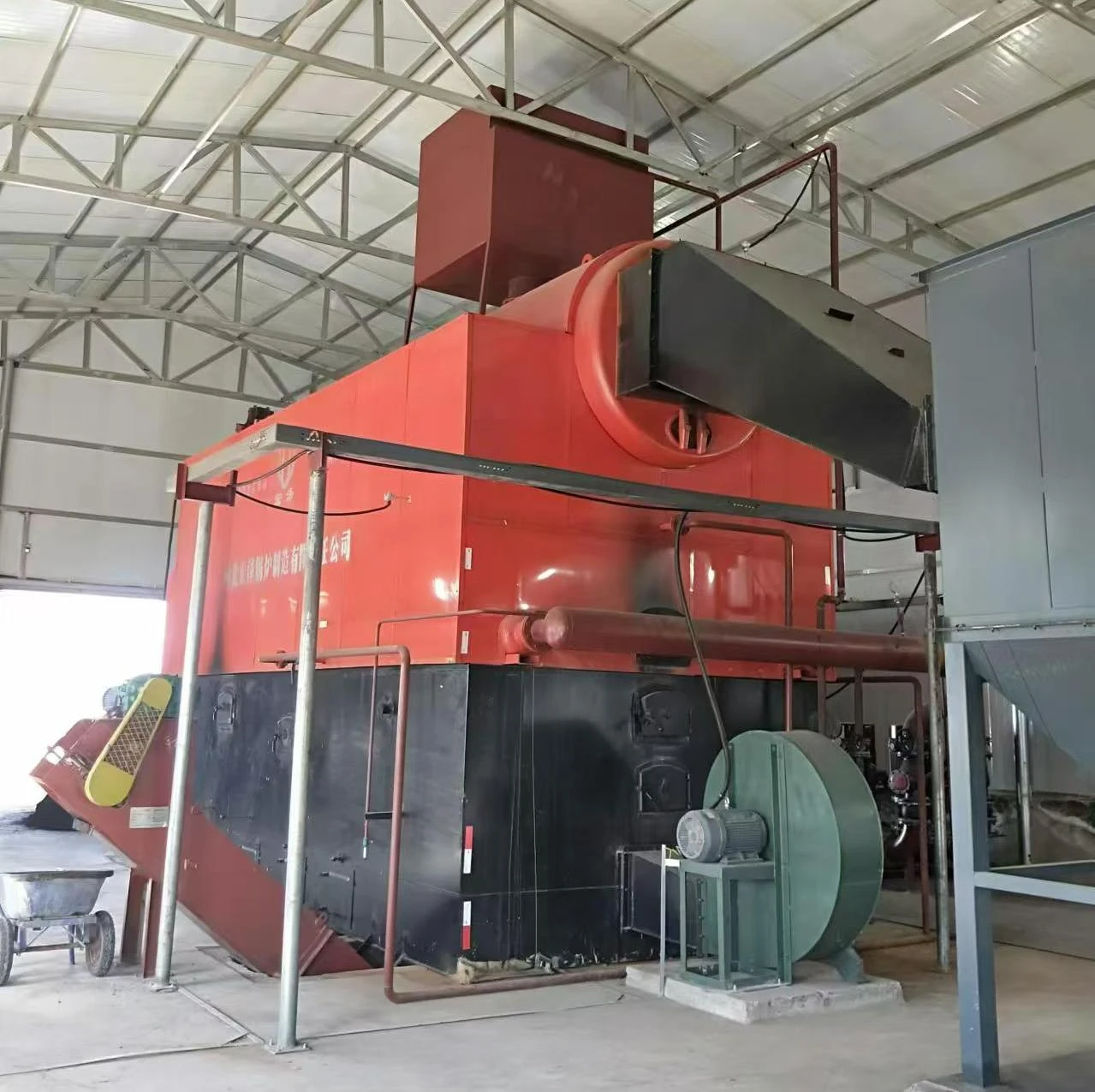
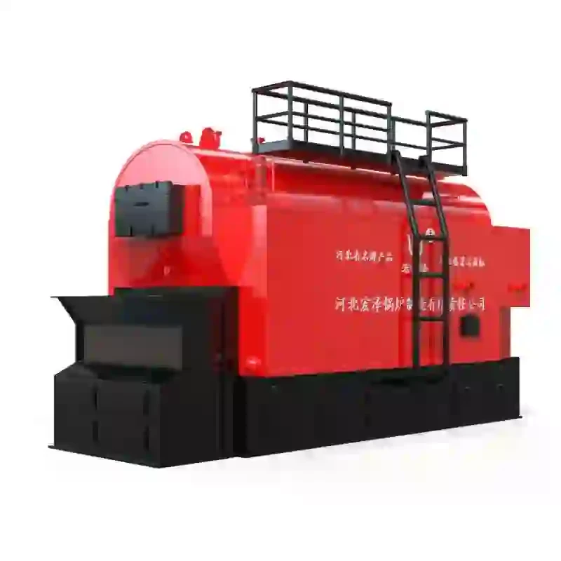
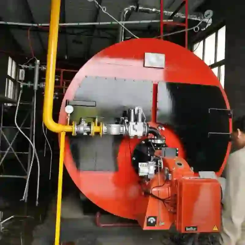
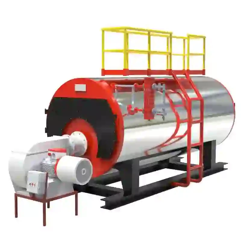
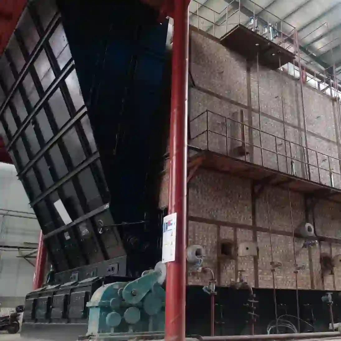
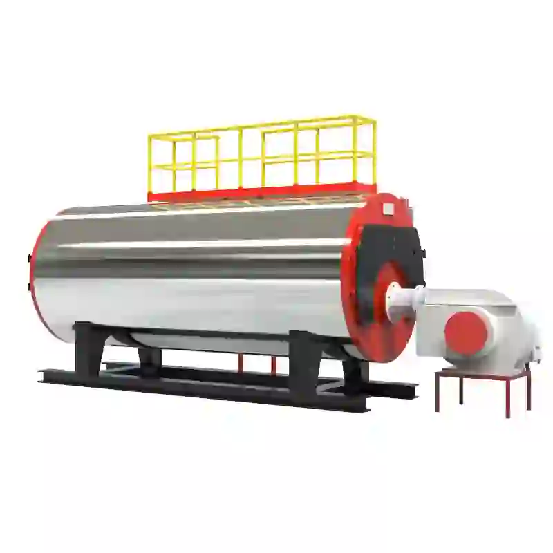
steam boiler schematic diagram
Understanding Steam Boiler Schematic Diagrams
Steam boilers are essential components in various industries, providing steam for heating, power generation, and various industrial processes. A steam boiler schematic diagram is a visual representation that illustrates the key elements and functions of a steam boiler system. Understanding these diagrams is crucial for engineers, technicians, and operators who work with steam boilers in their daily operations.
What is a Steam Boiler?
A steam boiler is a closed vessel that uses heat energy to convert water into steam. This steam then carries heat energy to different applications, making it an efficient way to transfer energy. The functioning of a steam boiler relies on several key components, including the burner, combustion chamber, heat exchanger, steam drum, water gauge, and safety valves, all of which are typically represented in a schematic diagram.
Key Components of a Steam Boiler Schematic Diagram
1. Burner The burner is responsible for generating heat through the combustion of fuel (such as natural gas, oil, or coal). In a schematic diagram, it is often depicted at the bottom of the boiler.
2. Combustion Chamber This is where the fuel is burned to create hot gases. The combustion chamber is connected to the burner and designed to maximize heat transfer to the water.
3. Heat Exchanger This component facilitates the transfer of heat from the flue gases produced during combustion to the water in the boiler. Proper design of the heat exchanger is crucial for the efficiency of the boiler.
4. Steam Drum The steam drum is where steam is collected and separated from water. In the schematic, it is usually shown at the top of the boiler. This component may also include internals like separators to ensure that only dry steam is generated.
5. Water Gauge This component allows operators to monitor the water level inside the boiler. An accurate water level is crucial for safe and efficient boiler operation, and it is depicted in the schematic with indicators showing minimum and maximum levels.
6. Safety Valves These are critical for preventing excessive pressure build-up within the boiler. Safety valves are often illustrated on the schematic diagram and are designed to open automatically when the pressure exceeds safe limits.
steam boiler schematic diagram

7. Pumps Feedwater pumps, shown in the schematic, supply water to the boiler, while condensate pumps help in recycling steam back into water. These pumps are essential for maintaining the continuous operation of the system.
8. Blowdown Valve This component allows the operator to remove impurities and sludge from the boiler. Regular blowdown is vital for maintaining water quality and overall system efficiency.
Reading the Schematic Diagram
A steam boiler schematic diagram can be complex, but understanding it is essential for anyone involved in the operation or maintenance of a boiler system. The diagram typically uses standardized symbols to represent the various components, making it easier to interpret. Knowing what each component does and how they interact with one another is key.
When examining the schematic, pay attention to the flow paths indicated by arrows. These arrows show how water, steam, and flue gases move through the system. Understanding these flow paths helps in diagnosing problems and ensuring that the system operates efficiently.
Importance of Schematic Diagrams
Schematic diagrams serve several purposes. They help in the design and construction of new boiler systems, provide guidance for troubleshooting and maintenance, and facilitate training for new personnel. By understanding how the components of a steam boiler interact, operators can ensure optimal performance and safety.
Moreover, schematic diagrams can assist in compliance with industry regulations. Many jurisdictions have stringent safety standards for steam boilers, and having a clear schematic can help ensure that all components are correctly installed and functioning.
Conclusion
In summary, steam boiler schematic diagrams are vital tools for understanding the intricate design and operation of steam boiler systems. By familiarizing oneself with the components and their interactions, individuals can contribute to the safe and efficient operation of boilers in various industrial applications. Whether one is designing, operating, or maintaining a steam boiler, the schematic diagram serves as an essential reference that supports best practices and enhances safety in the workplace.
-
Best Steam Boiler Design PDF Free Design Calculation & Diagram Downloads
NewsJun.10,2025
-
Hot Boiler Water Heater Efficient Heating Solutions for Home & Commercial Use
NewsJun.10,2025
-
Steam Boiler Safety Devices High-Quality Protection Valves
NewsJun.10,2025
-
Ultimate Steam Boiler Checklist for Safety & Efficiency
NewsJun.10,2025
-
Optimal Hot Water Boiler Temperature Setting Guide
NewsJun.10,2025
-
Effective Hot Water Boiler Chemical Treatment Protect & Maintain
NewsJun.09,2025
Related PRODUCTS


