Noy . 09, 2024 11:25 Back to list
Steam Boiler Layout and Design Schematic for Improved Efficiency and Performance Analysis
Understanding Steam Boiler Schematic Diagrams
Steam boilers are essential components in many industries, providing heat and power through the efficient conversion of water into steam. A well-designed steam boiler system not only improves the efficiency of energy use but also ensures safety and reliability. To comprehend how these intricate systems work, understanding a steam boiler schematic diagram is crucial.
What is a Steam Boiler?
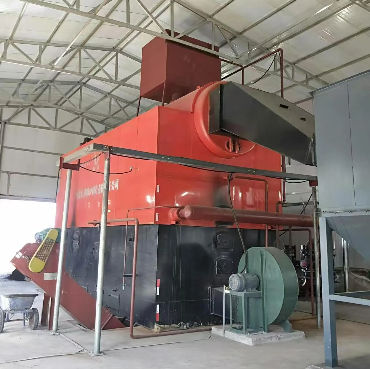
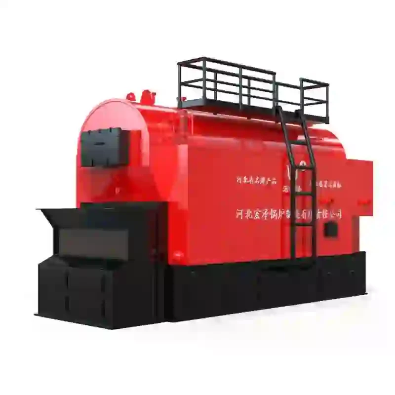
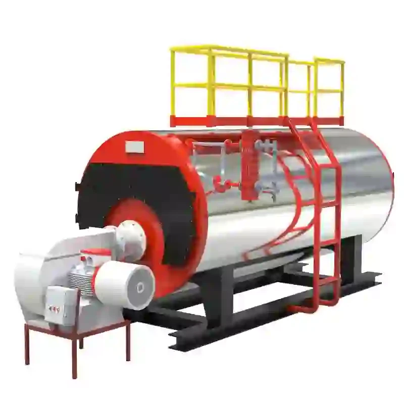
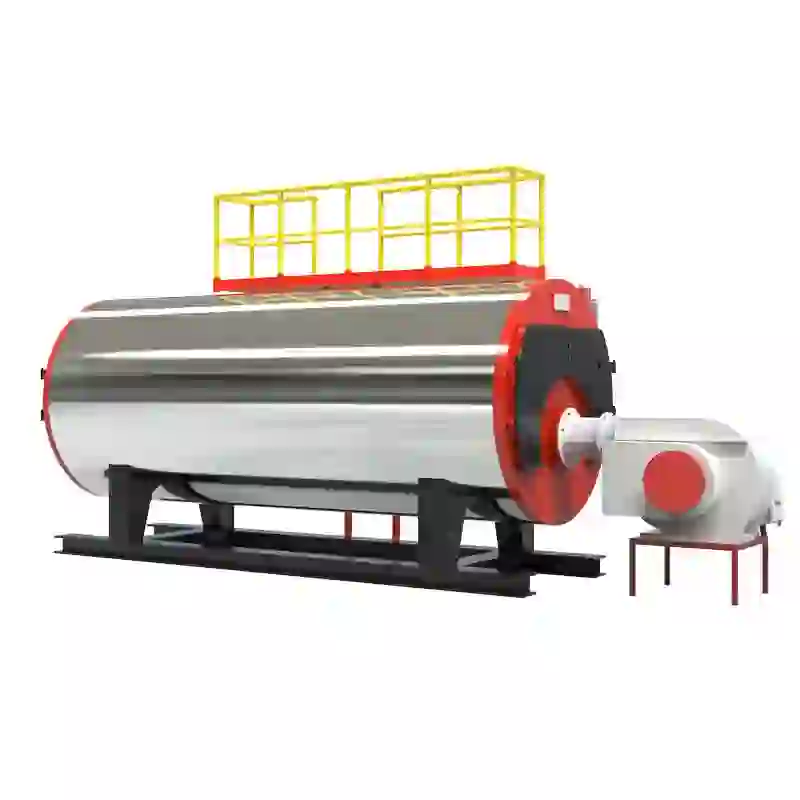
A steam boiler is a closed vessel designed to generate steam by applying heat energy to water. In many industrial applications, steam serves as a vital energy source, driving turbines and providing heat for various processes. The fundamental operation of a steam boiler involves several key components including a burner, boiler shell, water feed system, steam separation system, and an exhaust system.
Components of a Steam Boiler Schematic Diagram
Visualizing these components through a schematic diagram helps in understanding their interactions and functions. A typical steam boiler schematic diagram includes the following essential elements
1. Boiler Shell This is the outer structure of the boiler where water is heated. It is typically constructed from thick steel to withstand high pressure and temperature.
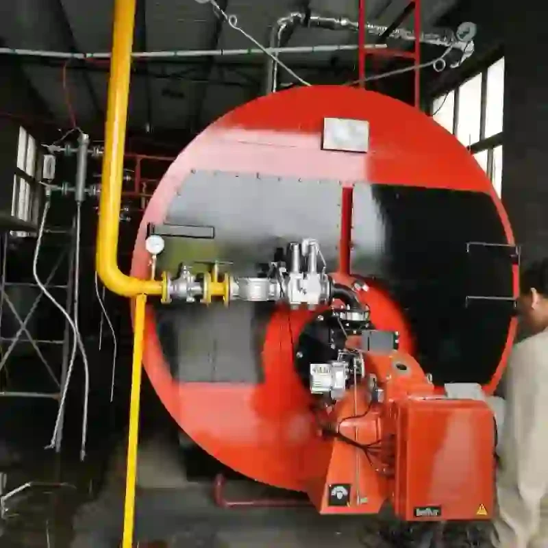
2. Burner The burner introduces fuel into the boiler. It mixes fuel with air and ignites it to produce hot gases, which transfer heat to the water inside the boiler.
3. Heat Exchanger This component is responsible for transferring heat from the burner to the water. As the hot gases flow over the heat exchanger, they heat the water, converting it to steam.
4. Water Feed System The feedwater system comprises pumps and valves that supply water to the boiler. It is essential for maintaining the appropriate water levels and ensuring continuous steam production.
steam boiler schematic diagram

5. Steam Drum The steam drum separates steam from water. Steam rises to the top of the drum, while excess water is returned to the heating section of the boiler.
6. Control System Automated controls manage the various functions of the boiler. This includes monitoring temperature, pressure, and water levels, and adjusting the operational parameters as needed to ensure optimal performance. 7. Safety Valves These are critical safety components that prevent the pressure inside the boiler from exceeding safe limits. They open automatically if pressure gets too high, releasing steam until the pressure drops to a safe level.
Reading a Schematic Diagram
To effectively read a steam boiler schematic diagram, one must understand the symbols and notations used. Each component is represented by specific shapes and lines. For example, a circle often symbolizes a pump while a triangle might represent a valve. Understanding these symbols is essential for diagnosing issues and performing maintenance on the system.
When analyzing the schematic, it is important to trace the flow of water and steam within the system. Starting from the feedwater entering the boiler, you should follow the heat transfer process as water turns into steam, then moves towards the steam drum, and finally exits through the steam outlet. This understanding aids in troubleshooting, identifying leakages, or assessing the overall efficiency of the boiler.
Importance of Understanding Schematic Diagrams
For engineers, technicians, and maintenance personnel, understanding the schematic diagram of a steam boiler is vital. It helps them gain insights into the operational mechanics, facilitates effective communication about system performance, and enhances their ability to maintain safety standards.
In industries that rely on steam boilers, such as manufacturing, power generation, and heating, the efficiency and reliability of steam systems directly affect production and operational costs. Thus, ensuring a strong grasp of steam boiler schematic diagrams can lead to better management practices and improved operational efficiency.
Conclusion
Steam boilers are intricate systems central to various industrial applications. A thorough understanding of steam boiler schematic diagrams enables professionals to effectively operate, maintain, and troubleshoot boiler systems. This knowledge not only enhances safety but also ensures optimal performance, paving the way for efficient energy use in a world increasingly focused on sustainability and economical resource management. The ability to interpret these diagrams is an invaluable skill in the toolkit of anyone working with steam systems.
-
Efficient Biomass Fired Hot Water Boiler | AI Heating Solution
NewsAug.01,2025
-
High-Efficiency Gas Thermal Oil Boilers | HPT Models
NewsJul.31,2025
-
Oil Fired Hot Water Boilers Sale - High Efficiency & Affordable
NewsJul.31,2025
-
High-Efficiency Commercial Oil Fired Steam Boiler for Industry
NewsJul.30,2025
-
High-Efficiency Biomass Fired Thermal Oil Boiler Solutions
NewsJul.30,2025
-
High Efficiency Gas Fired Thermal Oil Boiler for Industrial Heating
NewsJul.29,2025
Related PRODUCTS


