Jun . 28, 2024 13:40 Back to list
Gas-Fired Hot Water Boiler System Schematic Diagram
Understanding Gas-Fired Hot Water Boiler Diagrams
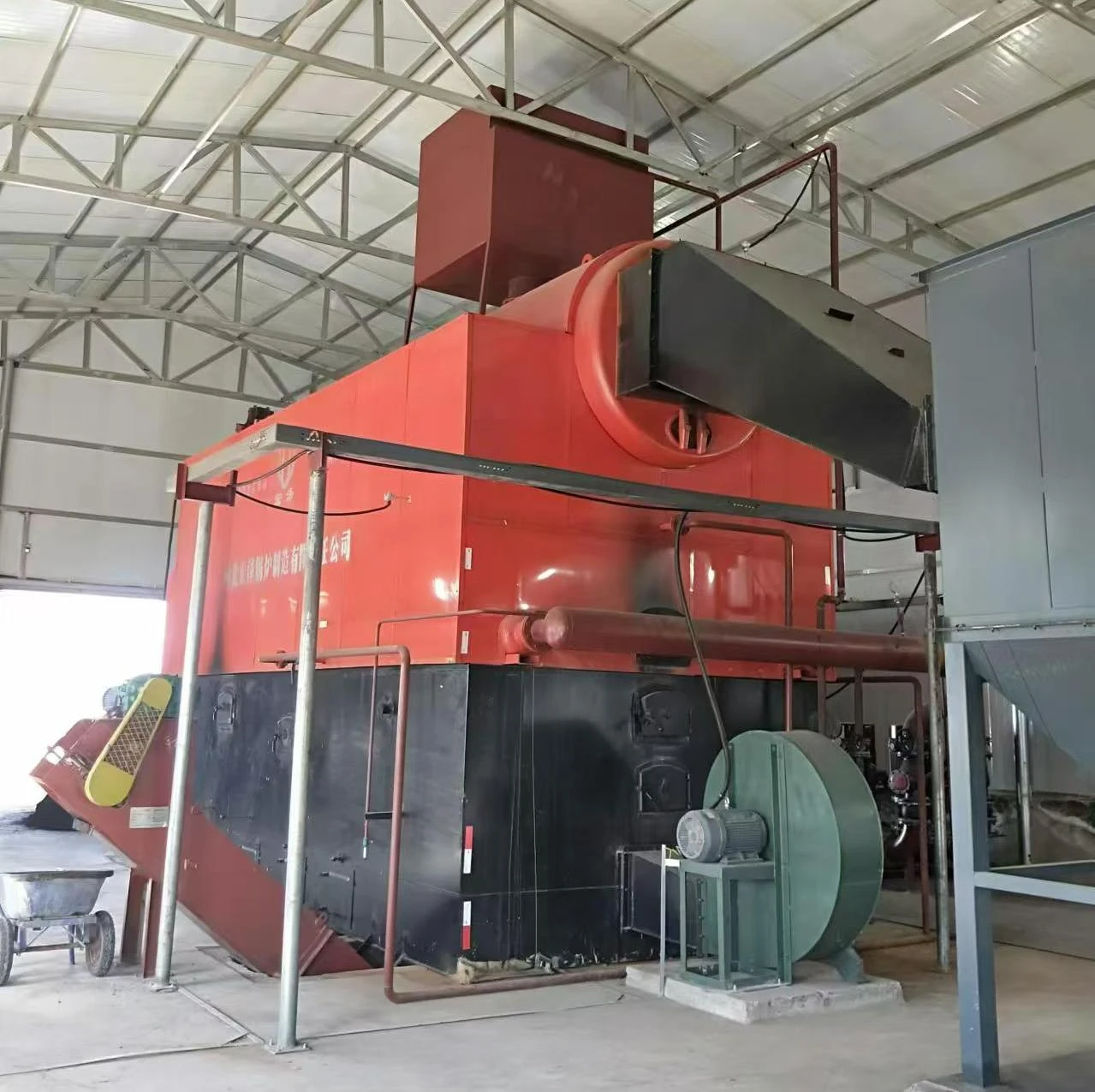
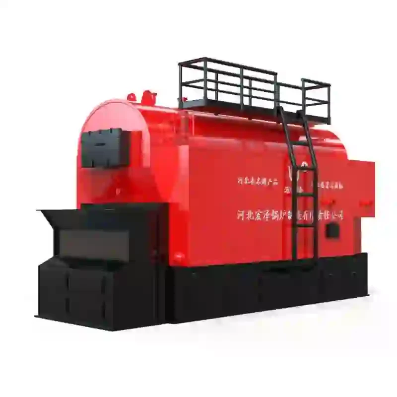
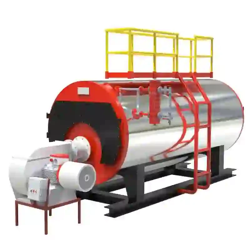
Gas-fired hot water boilers are an essential component of many heating systems, providing a reliable source of heat for homes and businesses. Understanding the diagram of such a boiler is crucial for proper maintenance, troubleshooting, and installation. In this article, we will delve into the key elements depicted in a typical gas-fired hot water boiler diagram and explain their functions.
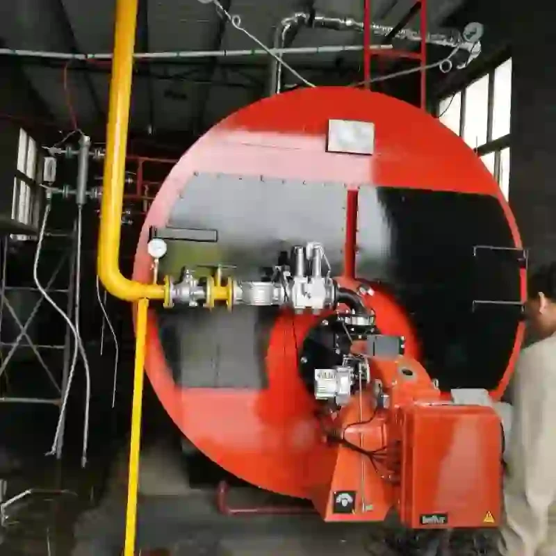
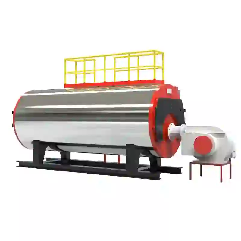
At the heart of the diagram is the boiler itself, represented by a rectangular shape with several connecting pipes and components. The boiler consists of a burner assembly, heat exchanger, and a flue outlet. The burner assembly, often located at the bottom of the boiler, mixes gas with air and ignites it to produce flames that heat up the heat exchanger. This process is usually indicated by a series of arrows showing the flow of gas and air, and a flame symbol representing the combustion process.
The heat exchanger, shown as a coiled tube or series of connected tubes inside the boiler, transfers the heat from the burning gas to the water flowing through it. The heated water then flows out of the boiler to circulate throughout the heating system. This circulation is typically represented by arrows within the pipes, indicating the direction of water flow.
A gas supply line, often marked with a gas in label, enters the diagram and connects to the burner assembly. This line may include a shutoff valve, pressure regulator, and a filter to ensure a steady and clean gas supply. These components are usually labeled clearly in the diagram for easy identification These components are usually labeled clearly in the diagram for easy identification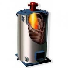 These components are usually labeled clearly in the diagram for easy identification These components are usually labeled clearly in the diagram for easy identification
 gas fired hot water boiler diagram.
Venting is another critical aspect of the gas-fired hot water boiler diagram. The flue gases, produced by the combustion of natural gas, must be safely expelled from the boiler through a vent pipe, which is usually drawn extending upwards from the boiler's top or side. This pipe leads to a chimney or other type of ventilation system, ensuring that harmful gases do not remain in the building.
Additionally, the diagram will show a pressure relief valve, temperature sensors, and a drain valve. These safety features are included to prevent overpressure and overheating scenarios. The pressure relief valve is typically depicted with an arrow pointing upwards, indicating its function to release excess pressure safely. Temperature sensors are often marked with a thermometer symbol, while the drain valve is shown at the lowest point of the boiler to allow for drainage during maintenance.
In conclusion, a gas-fired hot water boiler diagram is a detailed representation of the boiler's components and how they interact. By understanding the various parts and their functions, individuals can better maintain and operate these essential heating appliances. It is important to consult the specific diagram provided with your boiler model for precise details relevant to your unit.
 These components are usually labeled clearly in the diagram for easy identification These components are usually labeled clearly in the diagram for easy identification
 gas fired hot water boiler diagram.
Venting is another critical aspect of the gas-fired hot water boiler diagram. The flue gases, produced by the combustion of natural gas, must be safely expelled from the boiler through a vent pipe, which is usually drawn extending upwards from the boiler's top or side. This pipe leads to a chimney or other type of ventilation system, ensuring that harmful gases do not remain in the building.
Additionally, the diagram will show a pressure relief valve, temperature sensors, and a drain valve. These safety features are included to prevent overpressure and overheating scenarios. The pressure relief valve is typically depicted with an arrow pointing upwards, indicating its function to release excess pressure safely. Temperature sensors are often marked with a thermometer symbol, while the drain valve is shown at the lowest point of the boiler to allow for drainage during maintenance.
In conclusion, a gas-fired hot water boiler diagram is a detailed representation of the boiler's components and how they interact. By understanding the various parts and their functions, individuals can better maintain and operate these essential heating appliances. It is important to consult the specific diagram provided with your boiler model for precise details relevant to your unit.
 Share
Latest News
-
Efficient Biomass Fired Hot Water Boiler | AI Heating Solution
NewsAug.01,2025
-
High-Efficiency Gas Thermal Oil Boilers | HPT Models
NewsJul.31,2025
-
Oil Fired Hot Water Boilers Sale - High Efficiency & Affordable
NewsJul.31,2025
-
High-Efficiency Commercial Oil Fired Steam Boiler for Industry
NewsJul.30,2025
-
High-Efficiency Biomass Fired Thermal Oil Boiler Solutions
NewsJul.30,2025
-
High Efficiency Gas Fired Thermal Oil Boiler for Industrial Heating
NewsJul.29,2025
Related PRODUCTS
Copyright © 2025 HEBEI HONGZE BOILER MANUFACTURING CO., LTD. All Rights Reserved. Sitemap | Privacy Policy


