Oct . 06, 2024 08:11 Back to list
hot water boiler schematic diagram
Understanding the Hot Water Boiler Schematic Diagram
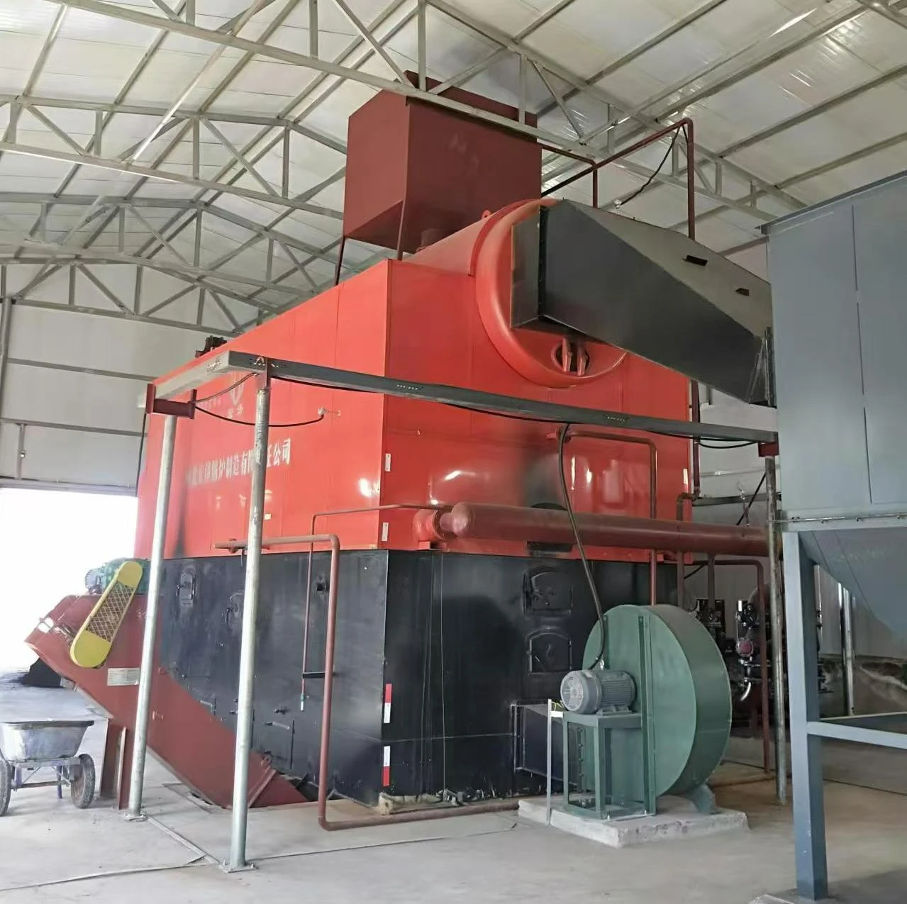
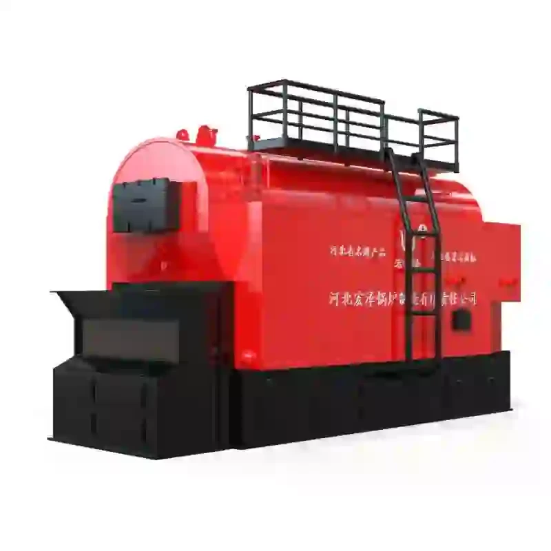
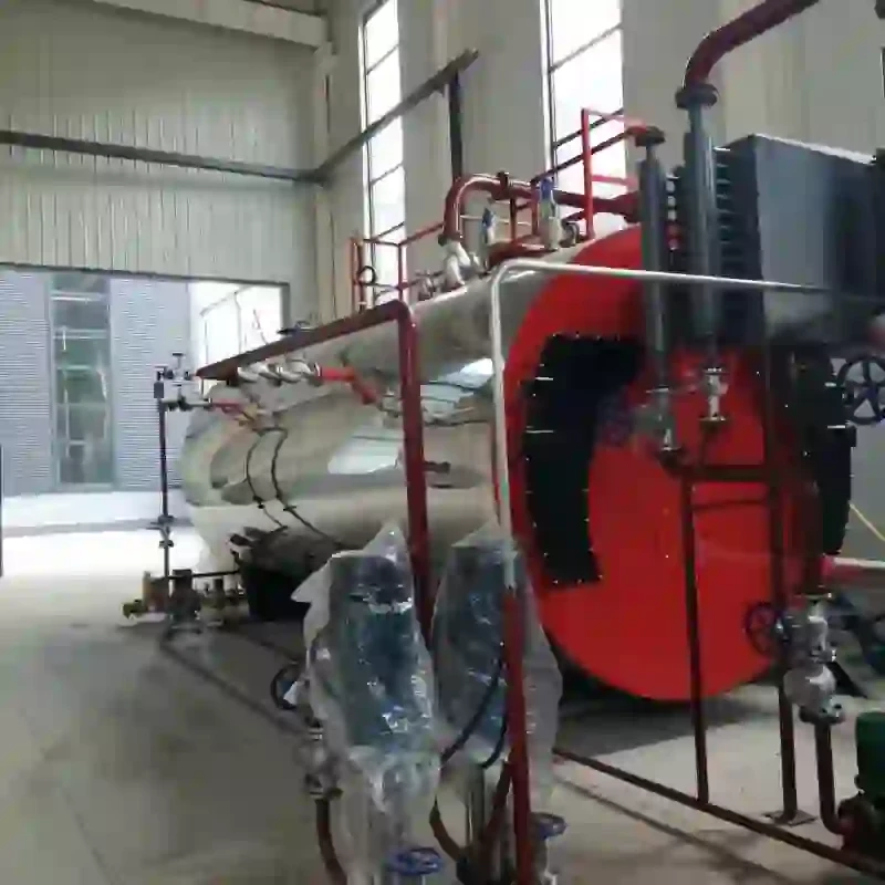
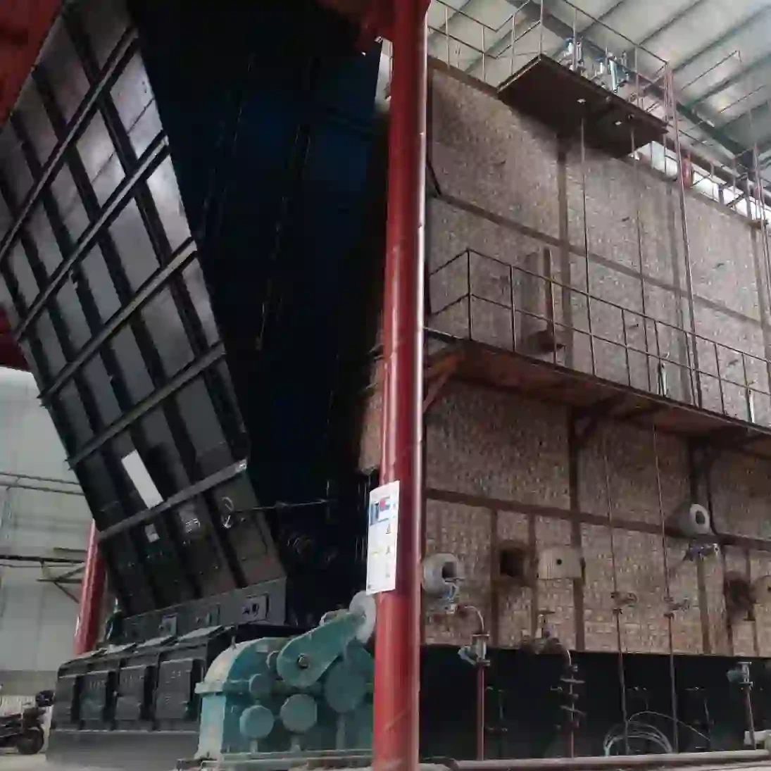
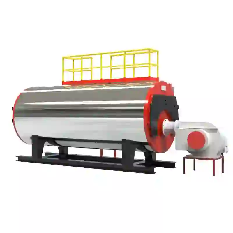
Hot water boilers play a crucial role in residential and commercial heating systems, providing a reliable source of hot water for various applications. Understanding the schematic diagram of a hot water boiler is essential for troubleshooting, maintenance, and optimizing performance. This article will explore the key components and functionality represented in a typical hot water boiler schematic.
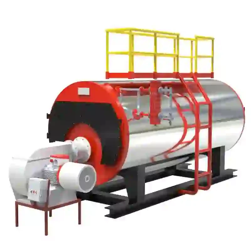
At its core, a hot water boiler operates on the principle of transferring heat from a fuel source—such as natural gas, oil, or electricity—to water. The schematic diagram helps visualize this process through various labeled components. The primary parts typically include the burner, heat exchanger, circulator pump, expansion tank, and various valves and controls.
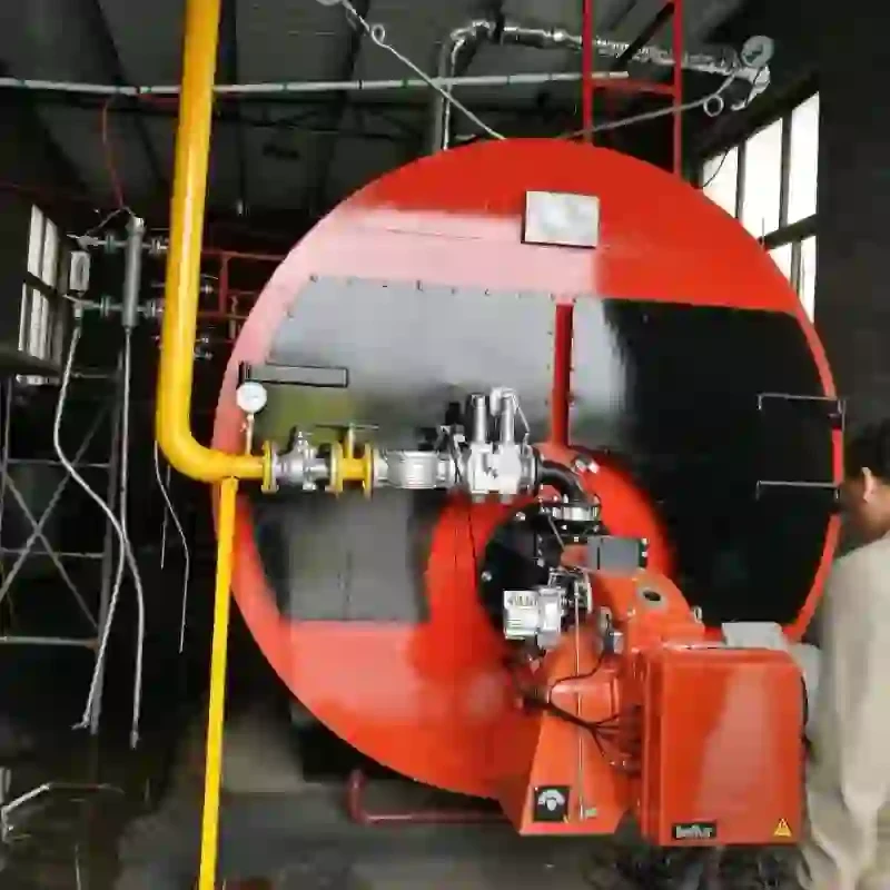
The burner is the heart of the hot water boiler. It ignites the fuel and generates heat, which is then transferred to the water. The heat exchanger is designed to maximize surface area contact between the hot gases produced by combustion and the water, ensuring efficient heat transfer. This component is critical as it dictates the boiler's efficiency and overall performance.
hot water boiler schematic diagram
Once heated, the water is circulated throughout the building by the circulator pump. This pump is typically located near the boiler and is responsible for moving the hot water through the pipes to various outlets, including faucets, radiators, or heating coils. The schematic diagram illustrates the flow paths, demonstrating how hot water circulates through the system and returns to the boiler for reheating.
An essential feature in most hot water boiler systems is the expansion tank. As water heats up, it expands, which can create excess pressure within the system. The expansion tank accommodates this change, preventing potential damage and ensuring safety. The schematic will indicate where the expansion tank is placed in the system to maintain pressure levels.
In addition to these components, the schematic diagram often includes various valves (such as safety relief valves) and control systems that regulate temperature, pressure, and flow. Understanding these controls is vital for efficient operation, as they help manage the system to maintain optimal performance and safety.
Overall, the schematic diagram of a hot water boiler serves as an invaluable tool for understanding the intricacies of the heating system. By familiarizing oneself with each component and its function, homeowners and technicians alike can improve maintenance practices, troubleshoot issues effectively, and ensure that the hot water boiler delivers consistent and efficient heating year-round. Whether for residential comfort or industrial applications, a well-understood schematic diagram is key to maximizing the benefits of hot water boiler technology.
-
High-Efficiency Commercial Oil Fired Steam Boiler for Industry
NewsJul.30,2025
-
High-Efficiency Biomass Fired Thermal Oil Boiler Solutions
NewsJul.30,2025
-
High Efficiency Gas Fired Thermal Oil Boiler for Industrial Heating
NewsJul.29,2025
-
High-Efficiency Gas Fired Hot Water Boiler for Sale – Reliable & Affordable
NewsJul.29,2025
-
High Efficiency Biomass Fired Hot Water Boiler for Industrial and Commercial Use
NewsJul.29,2025
-
High-Efficiency Biomass Fired Hot Water Boiler for Industrial Use
NewsJul.28,2025
Related PRODUCTS


