Dec . 06, 2024 22:24 Back to list
schematic diagram of steam boiler
Understanding the Schematic Diagram of a Steam Boiler
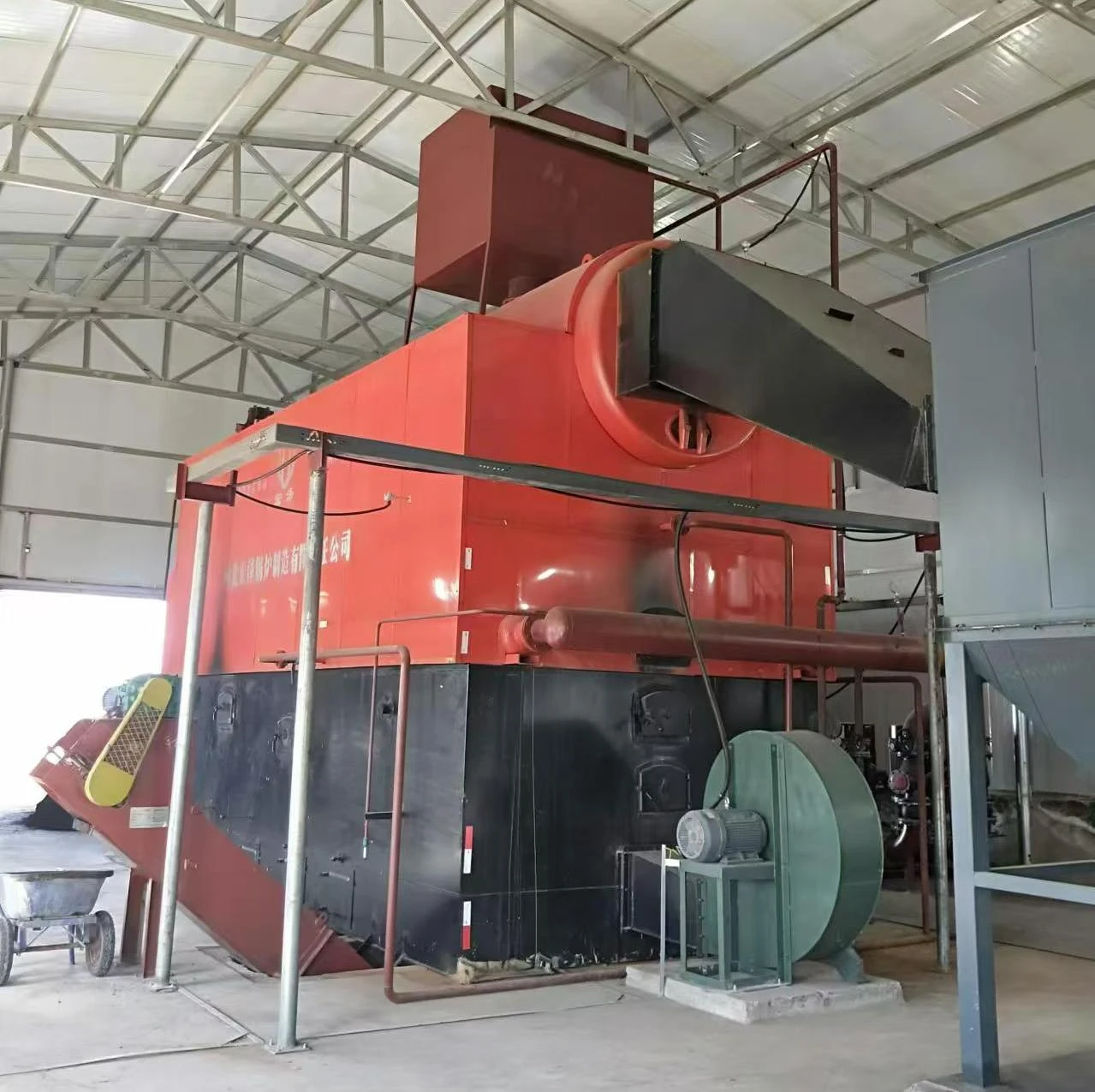
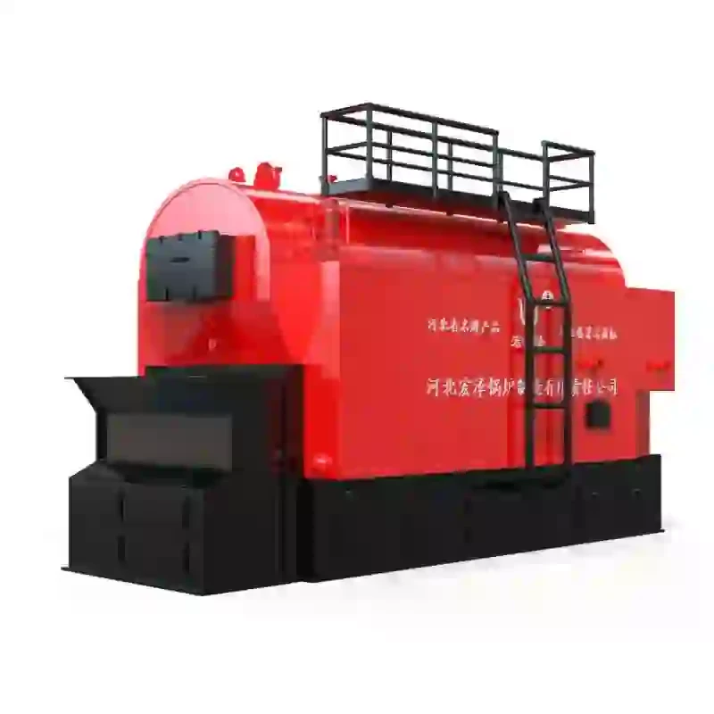
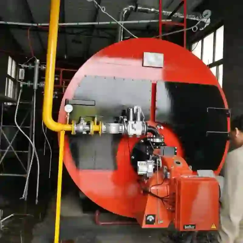
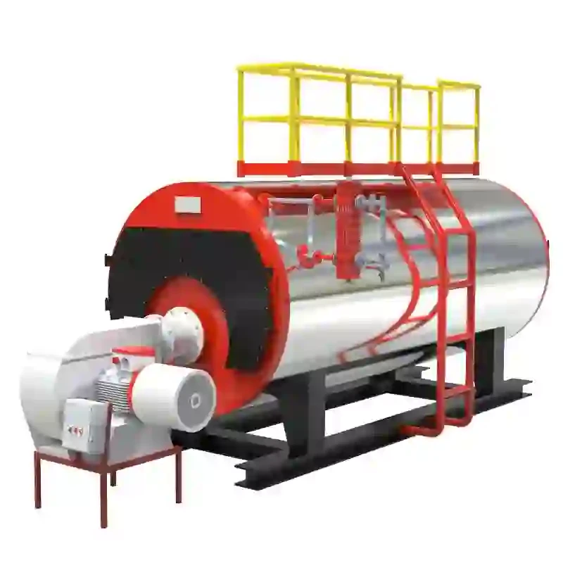
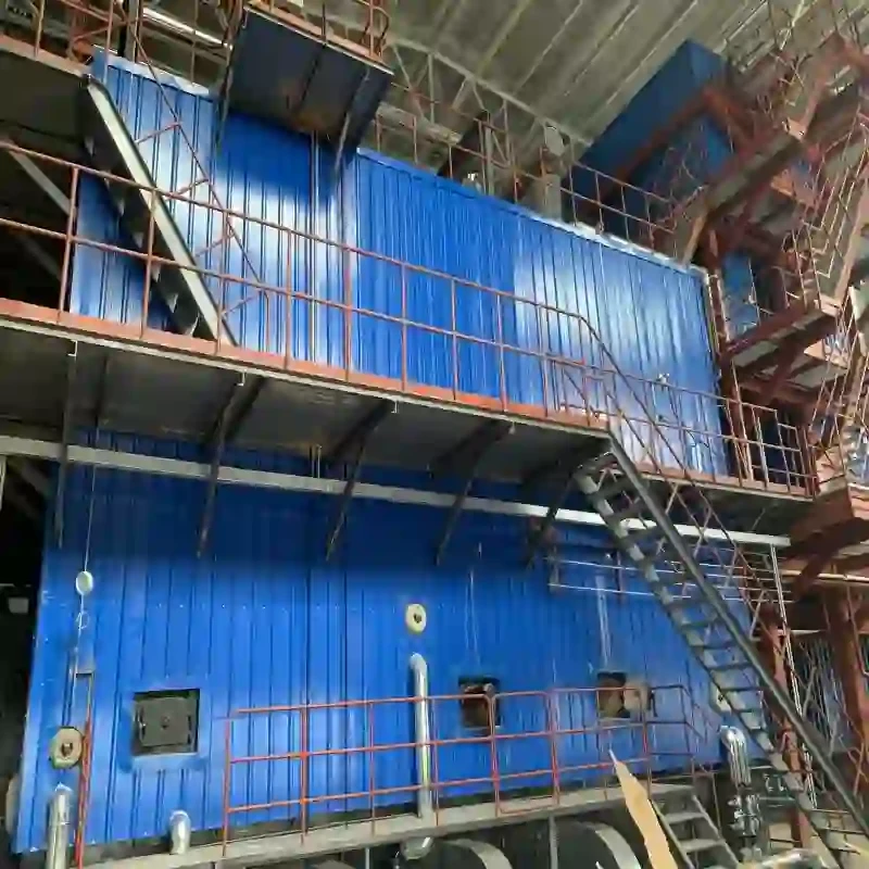
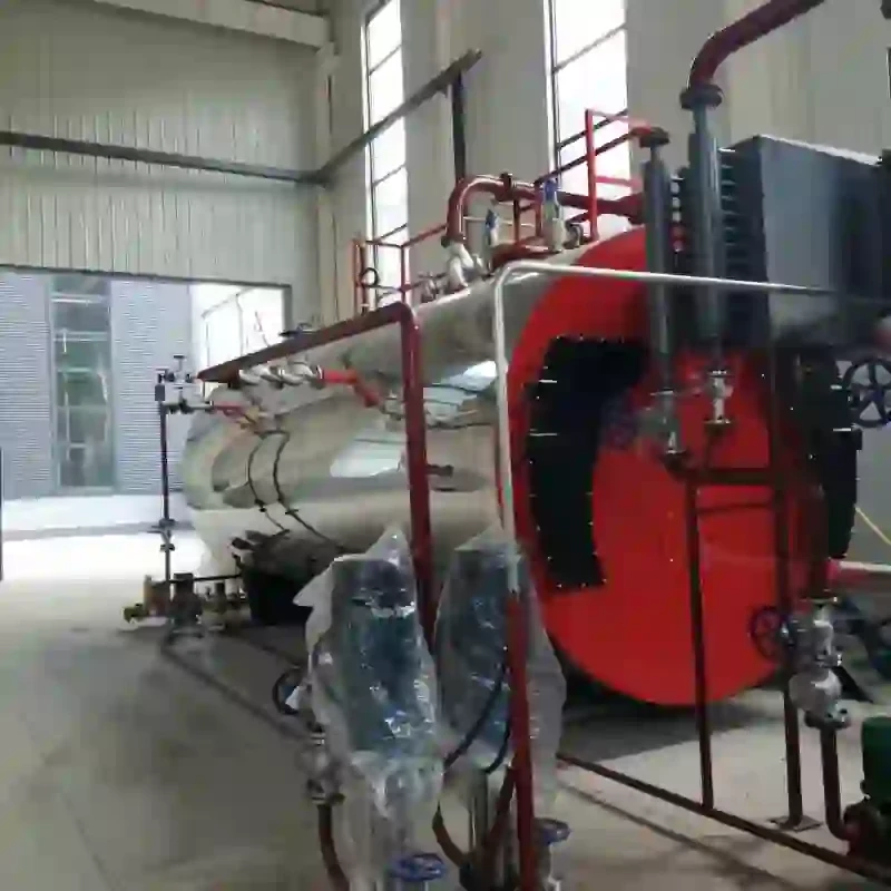
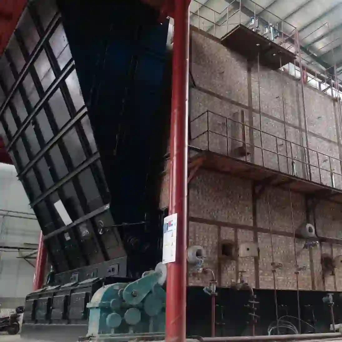
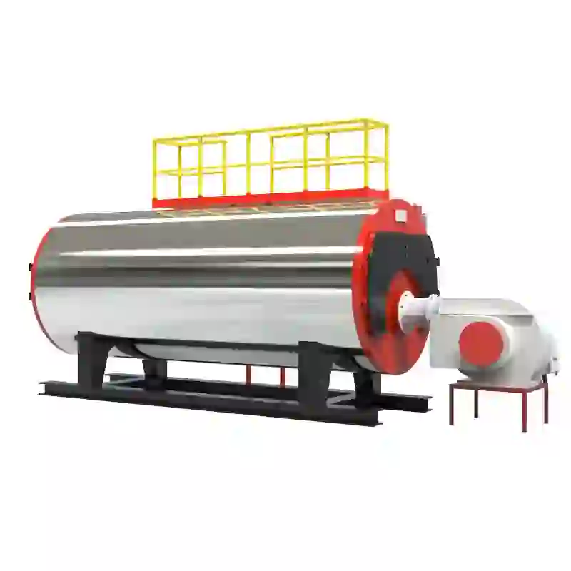
A steam boiler is an essential component in various industrial applications, generating steam for heating, power generation, and other processes. To grasp the operation of a steam boiler effectively, one must understand its schematic diagram, which illustrates the intricate relationships between its components and their functions. This article delves into the key elements of a steam boiler's schematic diagram and explains their roles in the steam generation process.
At its core, a steam boiler functions by converting water into steam through the application of heat. The schematic diagram typically displays several critical parts, including the furnace, heat exchanger, water supply system, steam drum, and ancillary equipment. Understanding these elements is vital for both the operation and maintenance of the boiler.
Understanding the Schematic Diagram of a Steam Boiler
2. Heat Exchanger The heat exchanger is a crucial component of the steam boiler, transferring heat from the combustion gases to the water. In the schematic diagram, this section is often shown as a network of tubes through which water flows. As the hot gases pass over these tubes, heat is transferred to the water, causing it to evaporate into steam. This efficient heat transfer is vital for maximizing the boiler's performance.
schematic diagram of steam boiler

3. Water Supply System A steam boiler requires a continuous supply of water, which is indicated in the schematic through various valves and pumps. The feed water is typically treated to remove impurities, which can cause scaling and corrosion within the boiler. The schematic diagram usually illustrates the feedwater pump, which pumps water into the boiler system, and the water level indicators that help monitor the water level in the steam drum. Maintaining the correct water level is essential for safe operation and efficiency.
4. Steam Drum The steam drum serves as a storage area for generated steam and is crucial for separating steam from water. In the schematic, it is typically depicted at the top of the boiler, where steam rises, and excess water drains back into the system. The steam drum's design ensures that only dry steam is delivered for use in heating or power generation, preventing issues related to water carryover.
5. Ancillary Equipment The schematic diagram will often include various ancillary devices, such as safety valves, pressure gauges, and blowdown valves. Safety valves are critical for maintaining safe operating pressure; they automatically release steam when pressure exceeds safe limits. Pressure gauges communicate the operational status of the boiler, providing vital information for monitoring. Blowdown valves remove accumulated impurities and sludge from the boiler water, essential for maintaining efficiency and longevity.
In conclusion, the schematic diagram of a steam boiler provides a comprehensive overview of its components and their interactions within the system. By understanding each part's role, operators can ensure optimal performance and safety. Regular maintenance and monitoring, facilitated by insights gained from the schematic, contribute significantly to the reliability and efficiency of steam boilers in industrial applications. Thus, a thorough knowledge of the steam boiler schematic is invaluable for anyone working within this critical industry.
-
High-Efficiency Commercial Oil Fired Steam Boiler for Industry
NewsJul.30,2025
-
High-Efficiency Biomass Fired Thermal Oil Boiler Solutions
NewsJul.30,2025
-
High Efficiency Gas Fired Thermal Oil Boiler for Industrial Heating
NewsJul.29,2025
-
High-Efficiency Gas Fired Hot Water Boiler for Sale – Reliable & Affordable
NewsJul.29,2025
-
High Efficiency Biomass Fired Hot Water Boiler for Industrial and Commercial Use
NewsJul.29,2025
-
High-Efficiency Biomass Fired Hot Water Boiler for Industrial Use
NewsJul.28,2025
Related PRODUCTS


