Dec . 12, 2024 10:41 Back to list
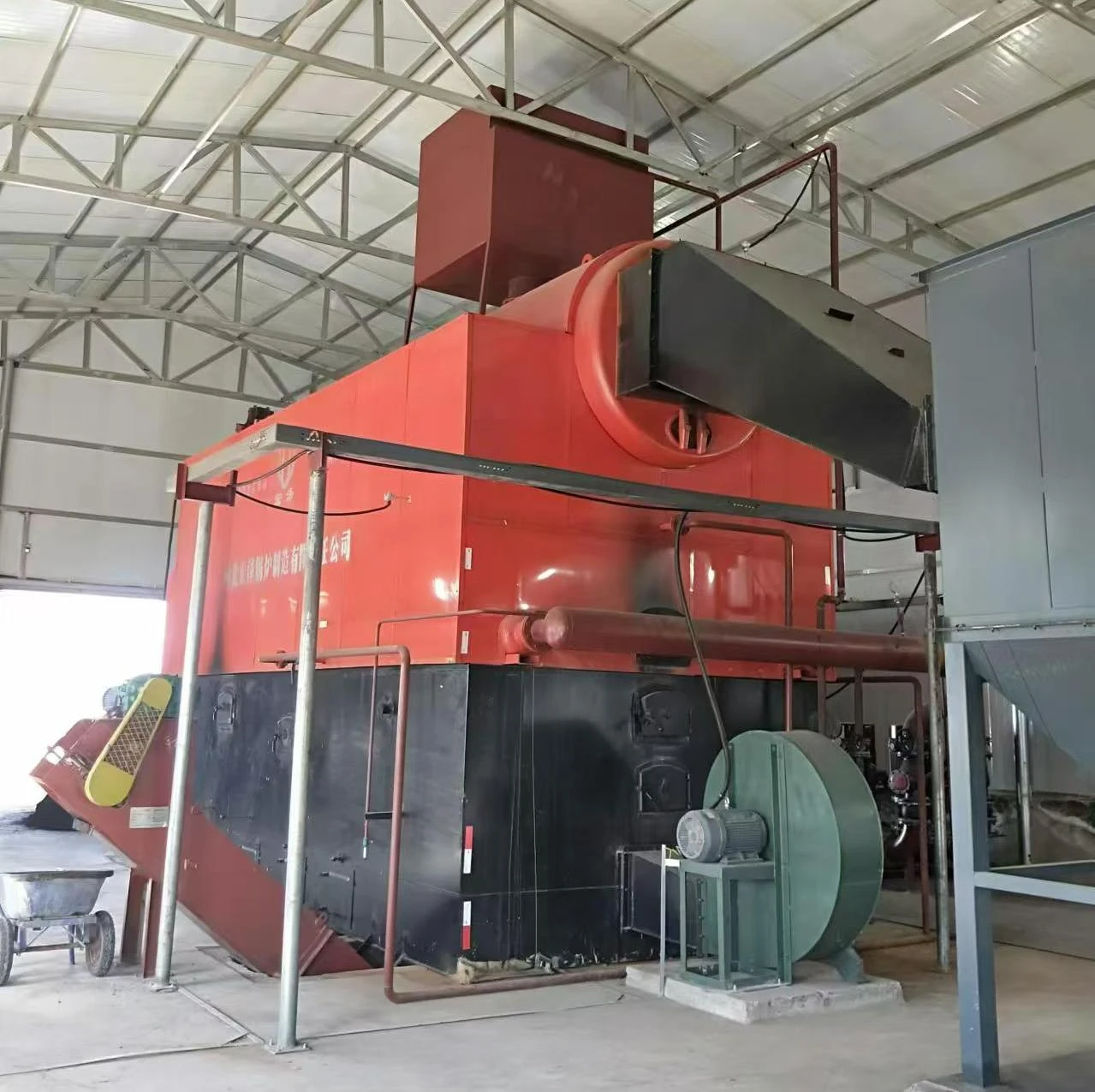
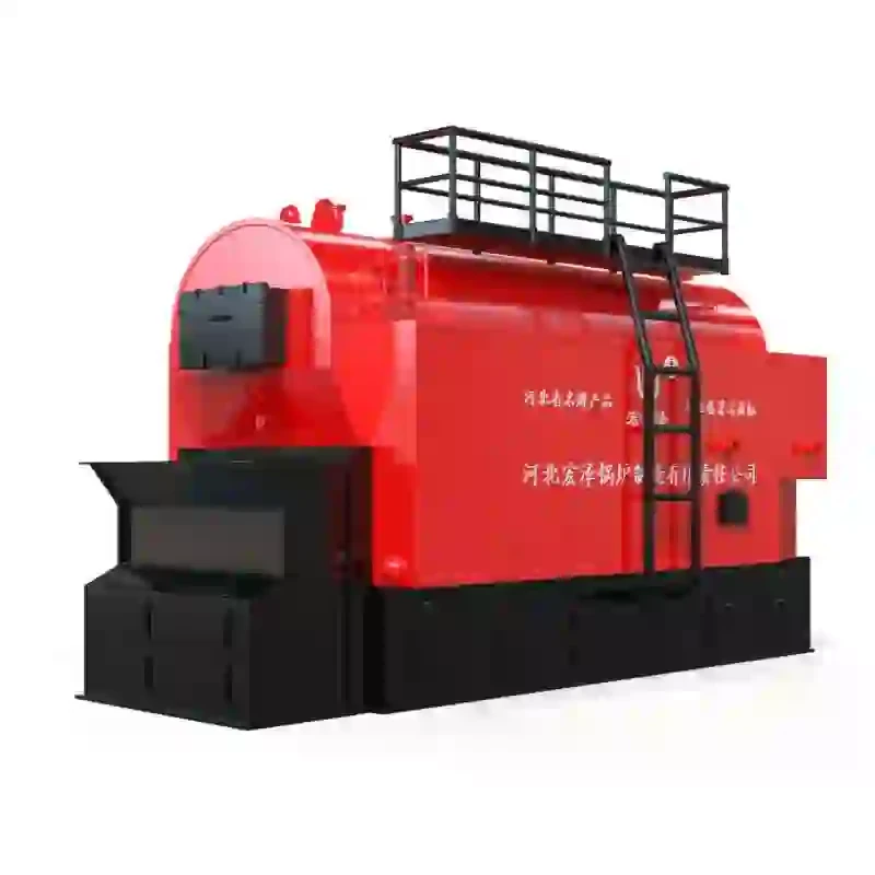
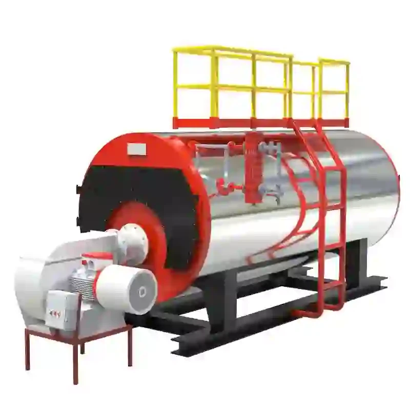
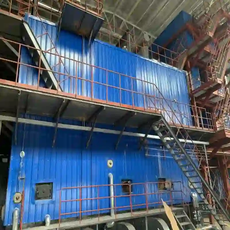
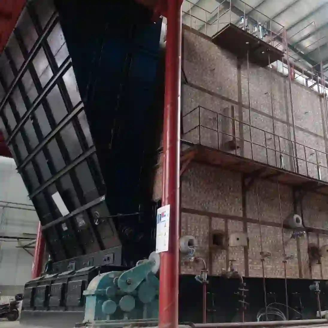
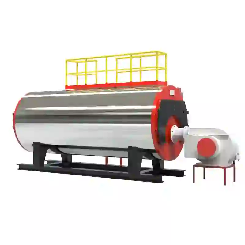
schematic diagram of steam boiler
Understanding the Schematic Diagram of a Steam Boiler
A steam boiler is an essential component in many industrial processes, where hot water or steam is needed for heating, power generation, or various other applications. To understand the functionality and complexity of a steam boiler, one must first familiarize themselves with its schematic diagram. This diagram serves as a blueprint, illustrating the various components and their interconnections, which is vital for operation, maintenance, and troubleshooting.
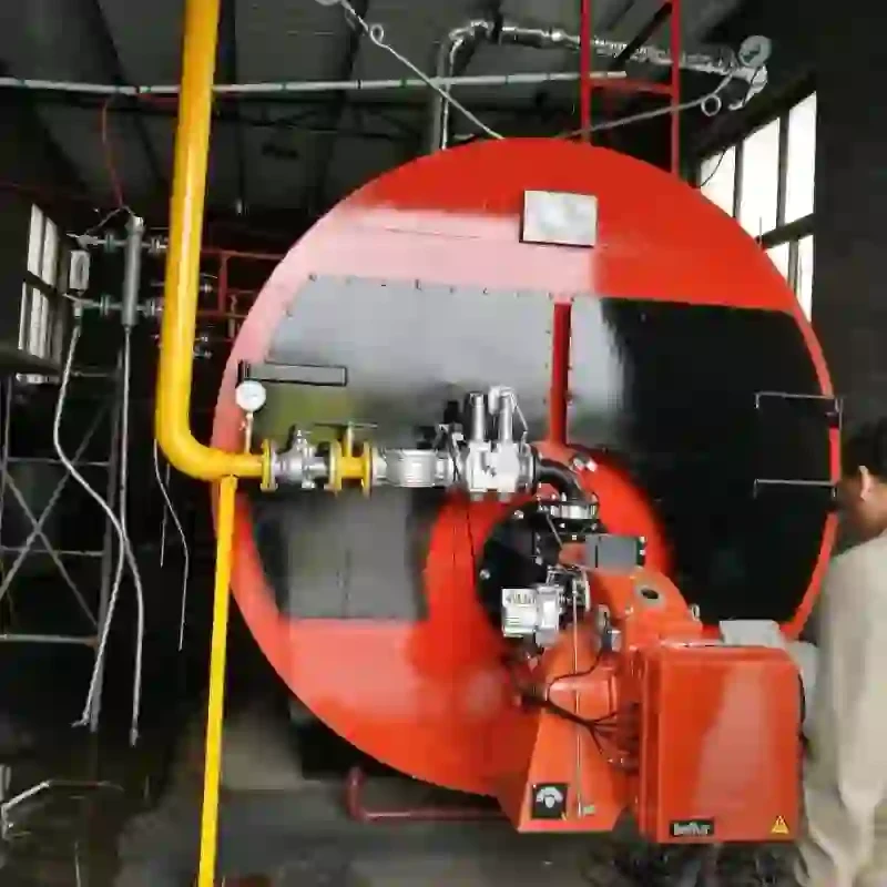
At the heart of the boiler is the combustion chamber, where fuel (which may be natural gas, coal, or oil) is burned to produce heat. The schematic typically illustrates the burner, responsible for mixing air and fuel to create an efficient flame. A well-designed combustion system minimizes emissions while maximizing thermal efficiency.
Understanding the Schematic Diagram of a Steam Boiler
The schematic also includes a water feed system, which is crucial for maintaining adequate water levels in the boiler. This system typically consists of make-up water pumps and valves that regulate the inflow of water. Maintaining the correct water level is vital, as too little water can lead to overheating and damage, while too much water can reduce steam production and efficiency.
schematic diagram of steam boiler

Another essential component represented in the schematic is the steam drum. Here, steam is separated from the water, allowing for high-quality steam to be extracted for use in turbines and other equipment. The steam drum usually contains a series of separation devices to ensure that only steam is drawn off, while any remaining water flows back into the boiler for re-heating. The proper functioning of the steam drum is crucial for maintaining system pressure and ensuring that steam quality meets required standards.
Safety is another critical aspect depicted in the schematic. Steam boilers operate under high pressure and temperature, making the incorporation of safety devices imperative. Features such as pressure relief valves, water level indicators, and safety shutdown systems help prevent accidents. The schematic often highlights these components, indicating their locations and connections to the main system, ensuring that operators can quickly identify and address any safety concerns.
Controls and instrumentation are also crucial elements of the steam boiler schematic. This includes various sensors and control systems that monitor temperature, pressure, and water levels, allowing for automated or manual adjustments to optimize performance. The control panel provides operators with vital data for monitoring the system health and making informed decisions regarding operation and maintenance.
In summary, a schematic diagram of a steam boiler is an invaluable tool that illustrates the complexity and interrelationships of the various components that comprise the system. Understanding this diagram is essential for anyone involved in the operation, maintenance, or design of steam boilers. By providing clear representations of the combustion system, heat exchange surfaces, water feed, steam drum, safety devices, and control systems, the schematic guides operators in ensuring efficient, safe, and reliable boiler operation. As industries continue to rely on steam boilers for their processes, a thorough comprehension of these schematics will remain a fundamental requirement for engineering and operational excellence.
-
Oil Fired Hot Water Boilers Sale - High Efficiency & Affordable
NewsJul.31,2025
-
High-Efficiency Commercial Oil Fired Steam Boiler for Industry
NewsJul.30,2025
-
High-Efficiency Biomass Fired Thermal Oil Boiler Solutions
NewsJul.30,2025
-
High Efficiency Gas Fired Thermal Oil Boiler for Industrial Heating
NewsJul.29,2025
-
High-Efficiency Gas Fired Hot Water Boiler for Sale – Reliable & Affordable
NewsJul.29,2025
-
High Efficiency Biomass Fired Hot Water Boiler for Industrial and Commercial Use
NewsJul.29,2025
Related PRODUCTS


