Oct . 31, 2024 15:00 Back to list
Schematic Representation and Functionality of a Steam Boiler System
Understanding the Schematic Diagram of a Steam Boiler
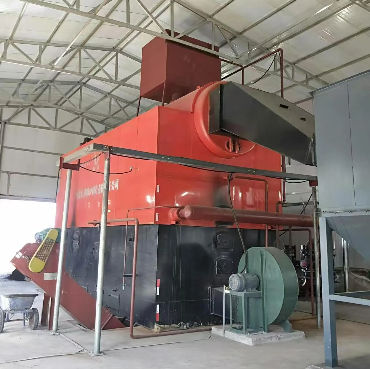
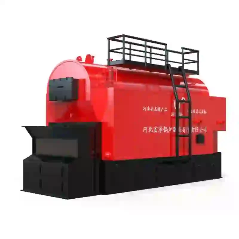
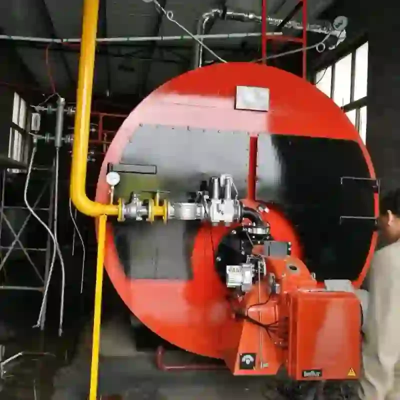
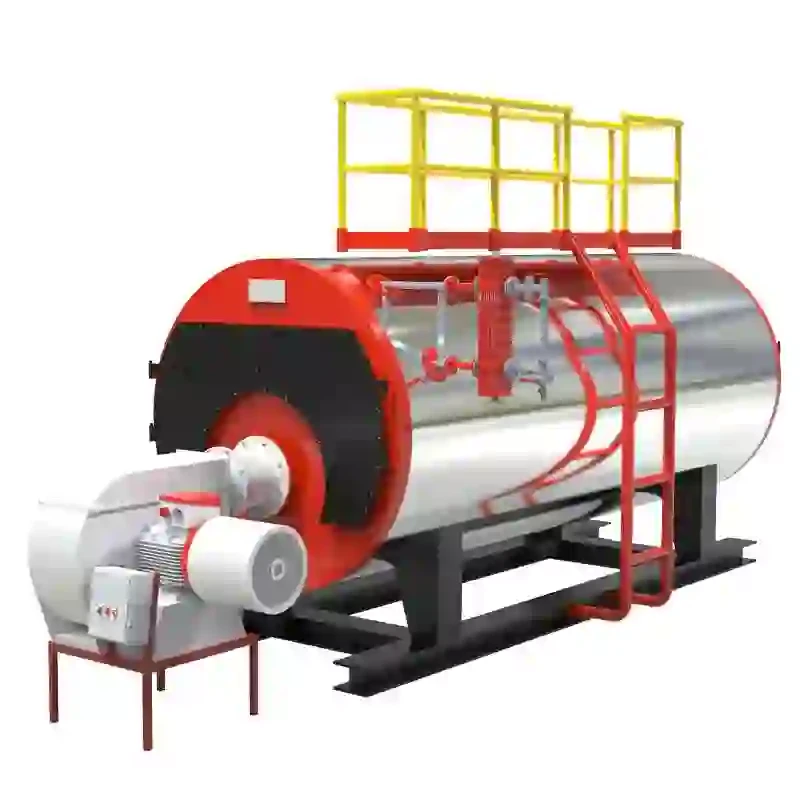
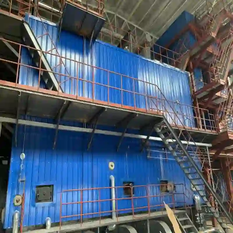
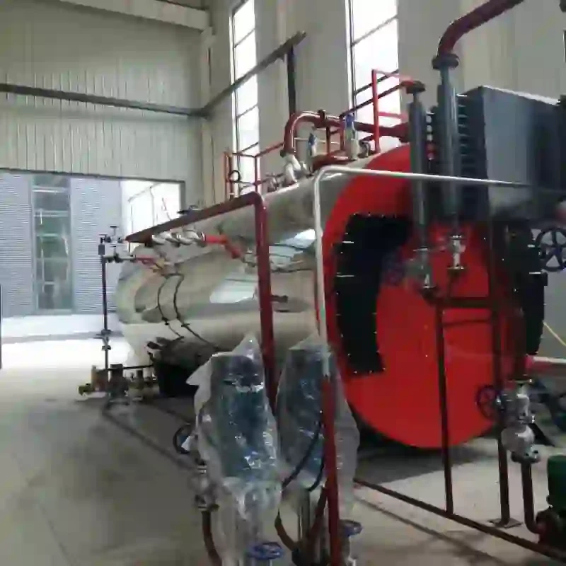
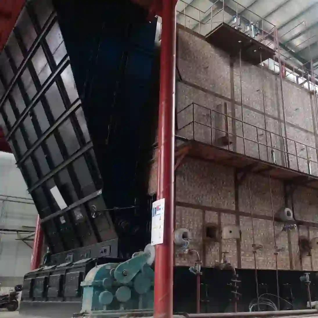
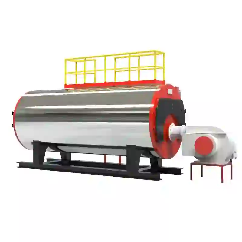
A steam boiler is an essential component in many industrial processes, providing steam for heating, power generation, and various applications in manufacturing. To grasp how a steam boiler functions, it is crucial to analyze its schematic diagram, which illustrates the components and their interconnections.
At its core, a steam boiler converts water into steam through the application of heat. The schematic diagram typically starts with the water supply system, where water is fed into the boiler from a municipal source or a storage tank. This is usually equipped with a level control system to maintain the appropriate water level necessary for efficient operation. Proper water level management is critical as it ensures that there is enough water to absorb the heat generated while preventing overheating and damage to the boiler.
Understanding the Schematic Diagram of a Steam Boiler
Once the water is heated sufficiently, it transforms into steam and begins to accumulate in the steam drum, another crucial aspect of the schematic diagram. The steam drum acts as a reservoir for the steam, allowing it to be separated from any remaining water. This component also includes pressure and temperature gauges to maintain optimal operating conditions. Monitoring these parameters is essential for safe boiler operation and efficiency.
schematic diagram of steam boiler

The steam produced can then be distributed to various pipelines, shown branching out from the steam drum in the schematic. These pipelines deliver steam to different areas of an industrial facility where it can be utilized for heating, driving turbines for electricity generation, or even in processes like sterilization in food production. It is vital that safety measures are in place, including relief valves depicted in the schematic, which prevent excessive pressure build-up in the system.
Moreover, the schematic diagram includes a return line for condensate, which is the residual water after steam has been used. This condensate can be captured and returned to the boiler for reheating, minimizing water waste and improving overall energy efficiency in the system. A well-designed boiler system thus includes both steam production and condensate recovery, creating a closed-loop system.
Finally, safety mechanisms such as water level alarms and pressure control systems are often depicted in the schematic. These ensure that the boiler operates within safe limits, providing alerts in case of malfunctions. Such features are crucial for safeguarding both the equipment and personnel operating in the vicinity.
In conclusion, a schematic diagram of a steam boiler provides an invaluable overview of its components and their functions. By understanding this diagram, engineers and technicians can optimize boiler performance, ensure safety, and enhance efficiency in industrial applications. Through the careful management of water supply, heat generation, steam distribution, and condensate recovery, steam boilers remain a cornerstone of many operational processes across various industries.
-
High-Efficiency Commercial Oil Fired Steam Boiler for Industry
NewsJul.30,2025
-
High-Efficiency Biomass Fired Thermal Oil Boiler Solutions
NewsJul.30,2025
-
High Efficiency Gas Fired Thermal Oil Boiler for Industrial Heating
NewsJul.29,2025
-
High-Efficiency Gas Fired Hot Water Boiler for Sale – Reliable & Affordable
NewsJul.29,2025
-
High Efficiency Biomass Fired Hot Water Boiler for Industrial and Commercial Use
NewsJul.29,2025
-
High-Efficiency Biomass Fired Hot Water Boiler for Industrial Use
NewsJul.28,2025
Related PRODUCTS


