Nov . 09, 2024 11:45 Back to list
Overview of Steam Boiler Schematic Diagram for Efficient Operation and Design
Understanding the Schematic Diagram of a Steam Boiler
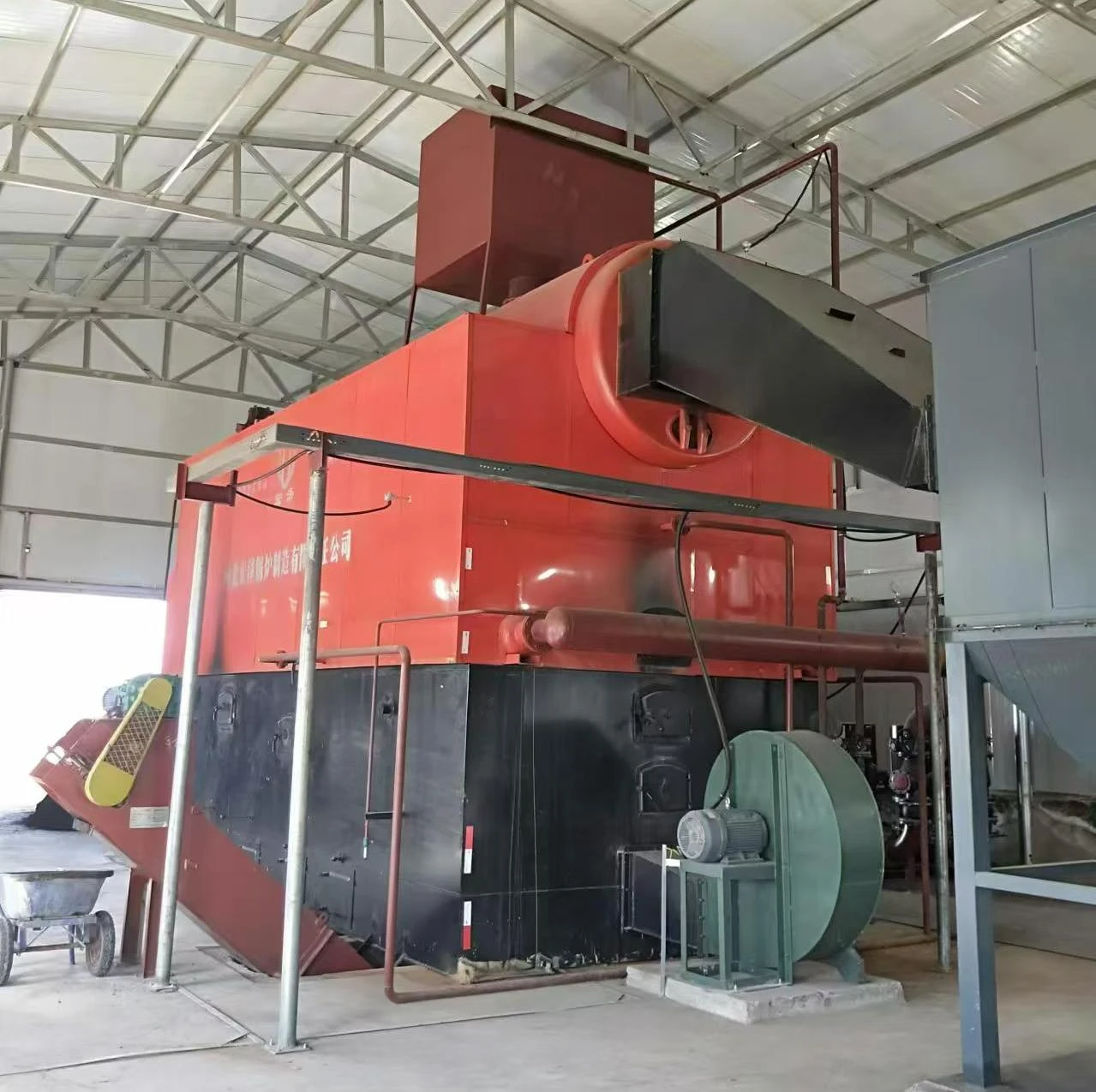
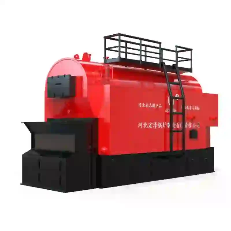
A steam boiler is an essential component in many industrial processes and facilities, enabling the efficient production of steam for heating, power generation, and various manufacturing applications. Understanding the schematic diagram of a steam boiler is crucial for engineers, technicians, and maintenance personnel, as it provides a visual representation of the complex components and their interconnections within the system. This article delves into the key elements of steam boiler schematic diagrams, explaining their functionalities, configuration, and importance in steam generation.
Overview of Steam Boilers
At its core, a steam boiler converts water into steam by applying heat. The heat source can be derived from different fuels, including natural gas, coal, oil, or even biomass. The generated steam is subsequently utilized for various applications such as powering turbines, providing heat for industrial processes, or supplying hot water for commercial use. The efficiency and safety of this process rely heavily on the proper function of the boiler's components, which are systematically illustrated in schematic diagrams.
Key Components of a Steam Boiler Schematic Diagram
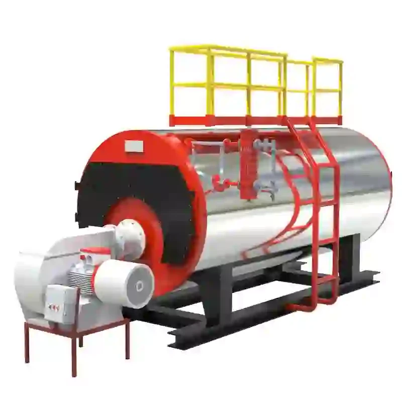
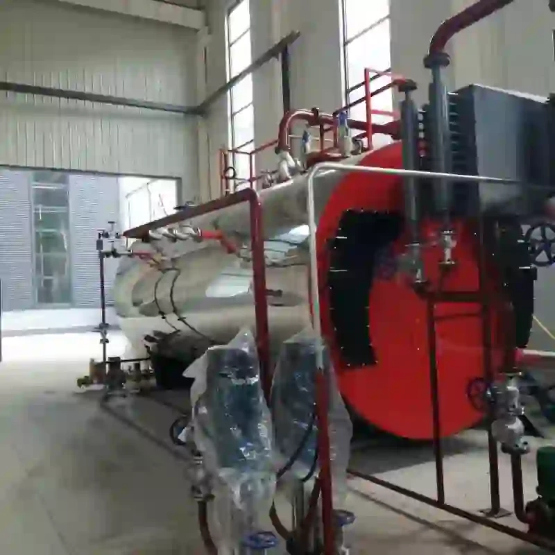
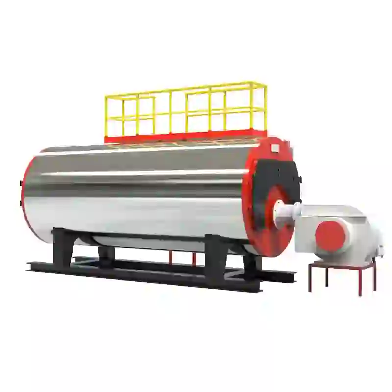
1. Boiler Shell The outer structure that houses the boiler and its internal mechanisms. It contains water and steam under pressure.
2. Fire Tubes or Water Tubes These are critical in transferring heat. In fire tube boilers, hot gases travel through tubes submerged in water, whereas water tube boilers have water flowing through tubes heated from outside by combustion gases.
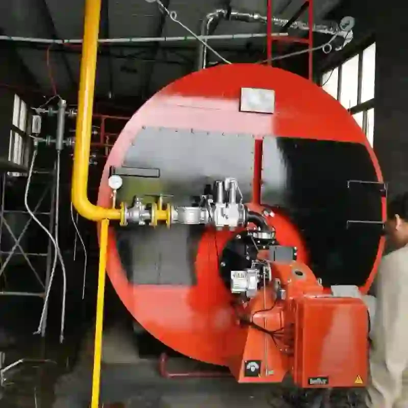
3. Burner This component initiates the combustion process. It mixes fuel and air in the correct ratio, ensuring efficient burning to produce heat. The design of the burner can significantly influence boiler performance and emissions.
4. Heat Exchanger Located within the boiler, the heat exchanger maximizes the transfer of heat from the combustion gases to the water. This helps in reducing fuel consumption and increasing efficiency.
5. Steam Drum A large cylindrical tank where steam is separated from water. This component ensures that only dry steam exits the boiler, which is essential for efficiency and safety in applications.
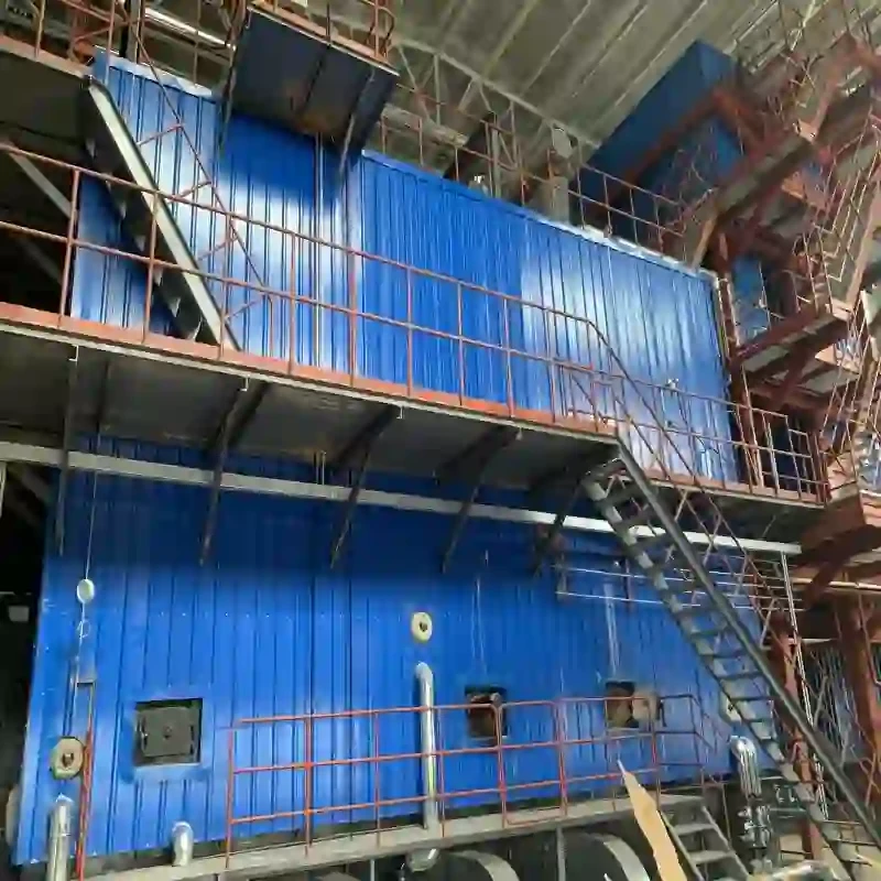
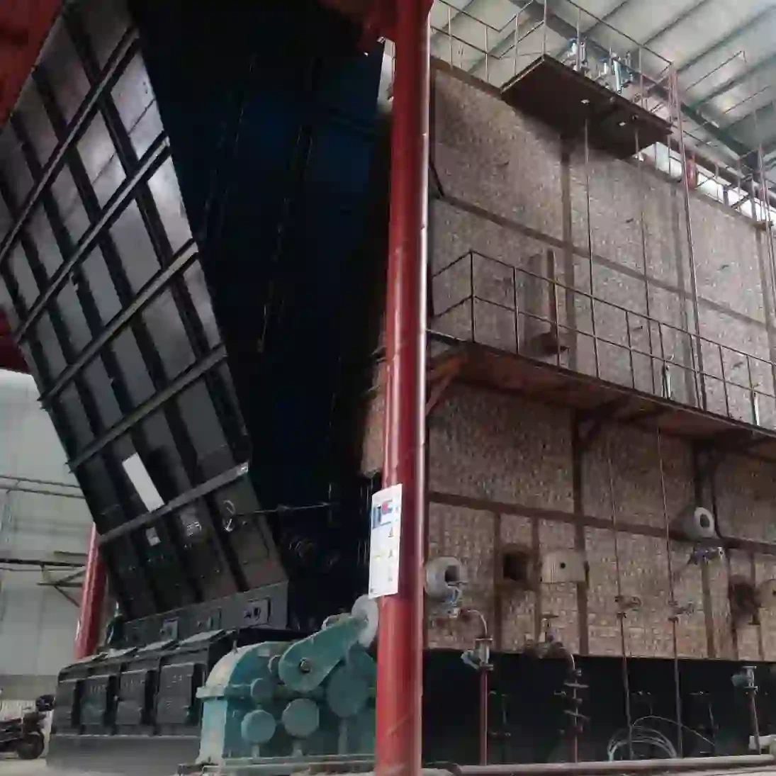
schematic diagram of steam boiler
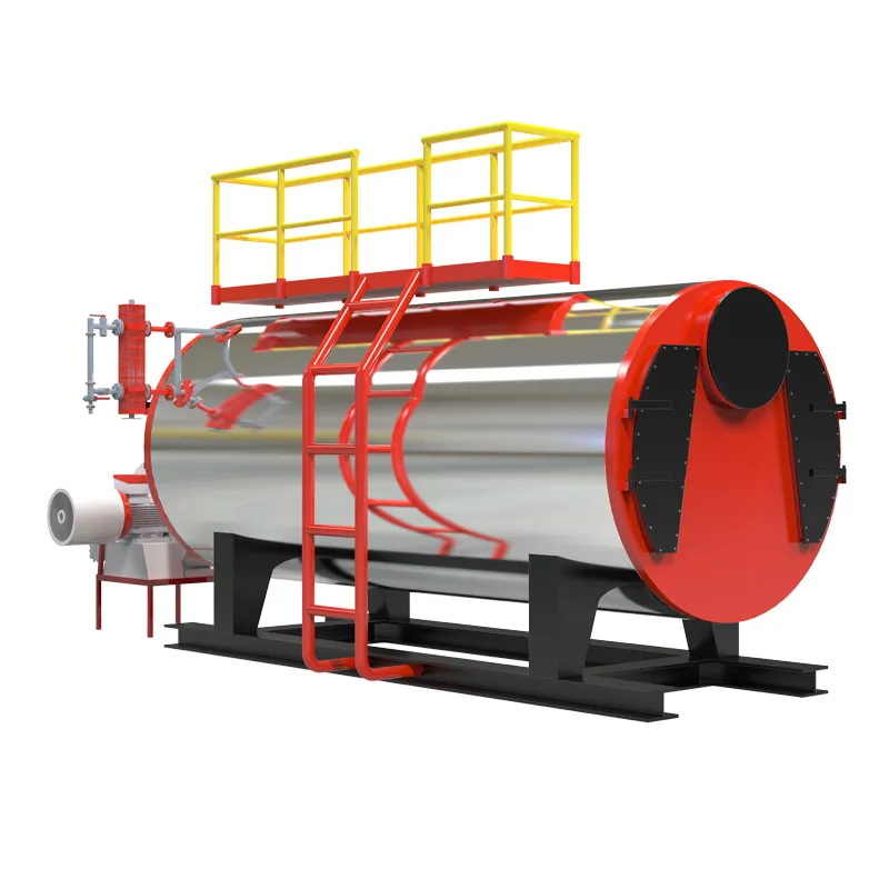
6. Feedwater System It includes all components involved in supplying water to the boiler. This typically consists of a feedwater pump, economizer (which pre-heats the feedwater), and a water treatment system to prevent scale and corrosion.
7. Safety Valves These are crucial for the safe operation of boilers, designed to release excess pressure that could otherwise lead to catastrophic failures. They prevent overpressure situations by venting steam or water if the pressure exceeds predetermined limits.
8. Control Systems Modern steam boilers incorporate sophisticated control systems to monitor and regulate various parameters such as pressure, temperature, and water levels. These systems ensure the boiler operates efficiently and within safe operational limits.
Importance of Understanding Schematic Diagrams
Schematic diagrams serve as a roadmap for understanding the configuration and operation of steam boilers. For engineers and technicians, being able to read and interpret these diagrams is vital for several reasons
- Troubleshooting When issues arise, a schematic provides a clear layout to identify potential problem areas quickly. - Maintenance Regular maintenance is crucial for effective boiler operation. Diagrams help in pinpointing the location of components that require inspection or servicing.
- Safety Compliance Adhering to safety standards is non-negotiable in boiler operation. Schematic diagrams outline safety features and emergency systems, ensuring operators can effectively manage risks.
- Training For new employees, understanding the schematic diagrams facilitates a quicker learning curve about the system’s operation and components.
Conclusion
The schematic diagram of a steam boiler encapsulates the essential components and their relationships, facilitating a comprehensive understanding of this vital system. With the correct interpretations, professionals can ensure efficient operation, enhance safety, and maintain optimal performance. As industries continue to rely on steam boilers for a variety of applications, the significance of these diagrams remains paramount in the ongoing quest for efficiency and reliability. This visualization tool not only aids in the effective management of boiler systems but also supports the development of more advanced and sustainable steam generation technologies.
-
High-Efficiency Commercial Oil Fired Steam Boiler for Industry
NewsJul.30,2025
-
High-Efficiency Biomass Fired Thermal Oil Boiler Solutions
NewsJul.30,2025
-
High Efficiency Gas Fired Thermal Oil Boiler for Industrial Heating
NewsJul.29,2025
-
High-Efficiency Gas Fired Hot Water Boiler for Sale – Reliable & Affordable
NewsJul.29,2025
-
High Efficiency Biomass Fired Hot Water Boiler for Industrial and Commercial Use
NewsJul.29,2025
-
High-Efficiency Biomass Fired Hot Water Boiler for Industrial Use
NewsJul.28,2025
Related PRODUCTS


