Sep . 22, 2024 19:54 Back to list
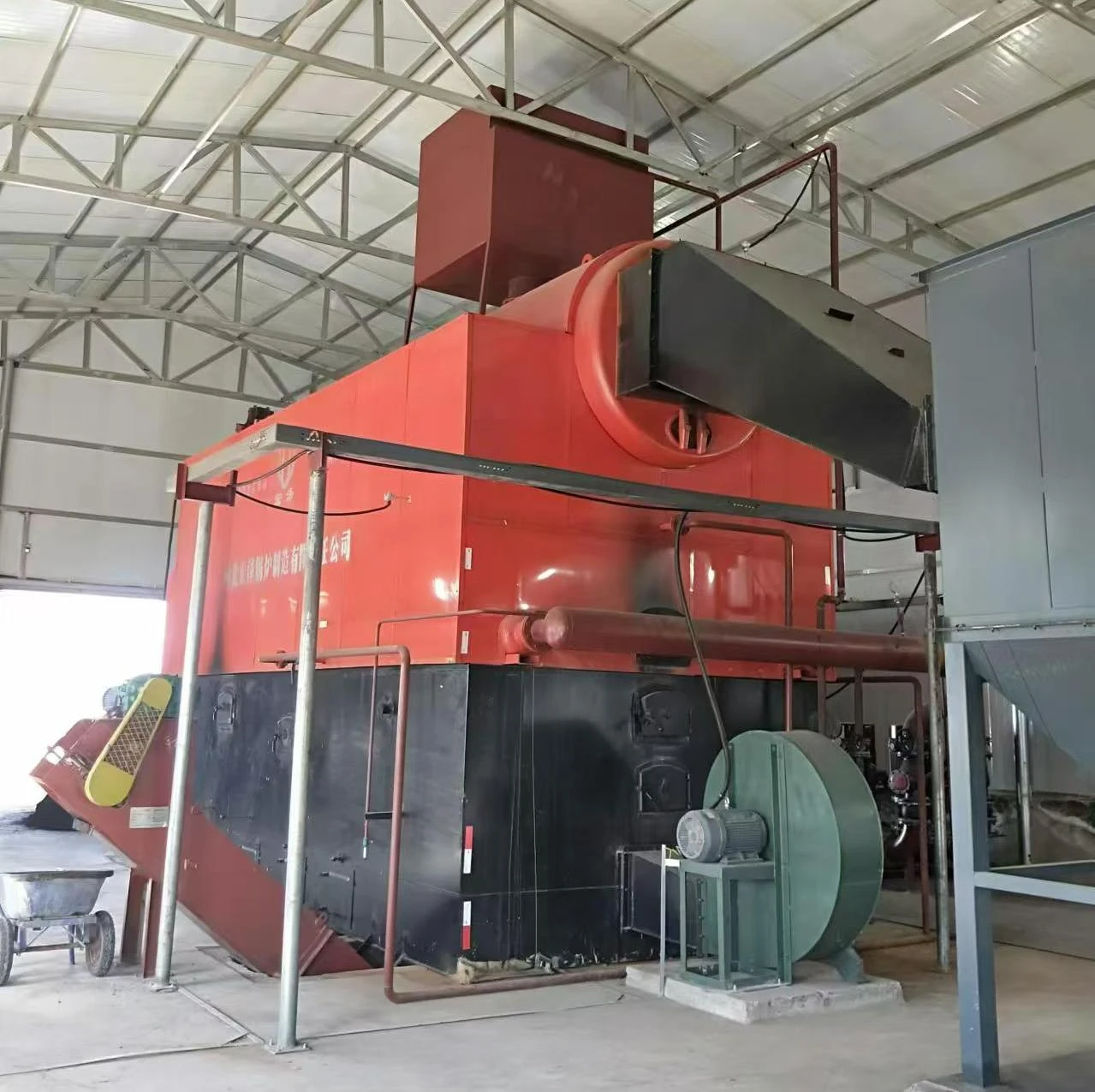
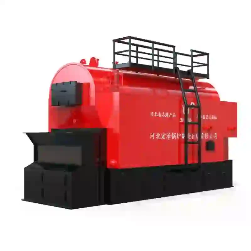
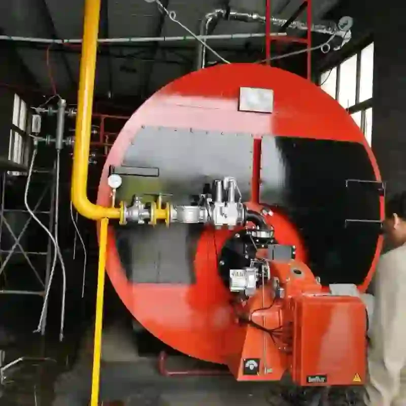
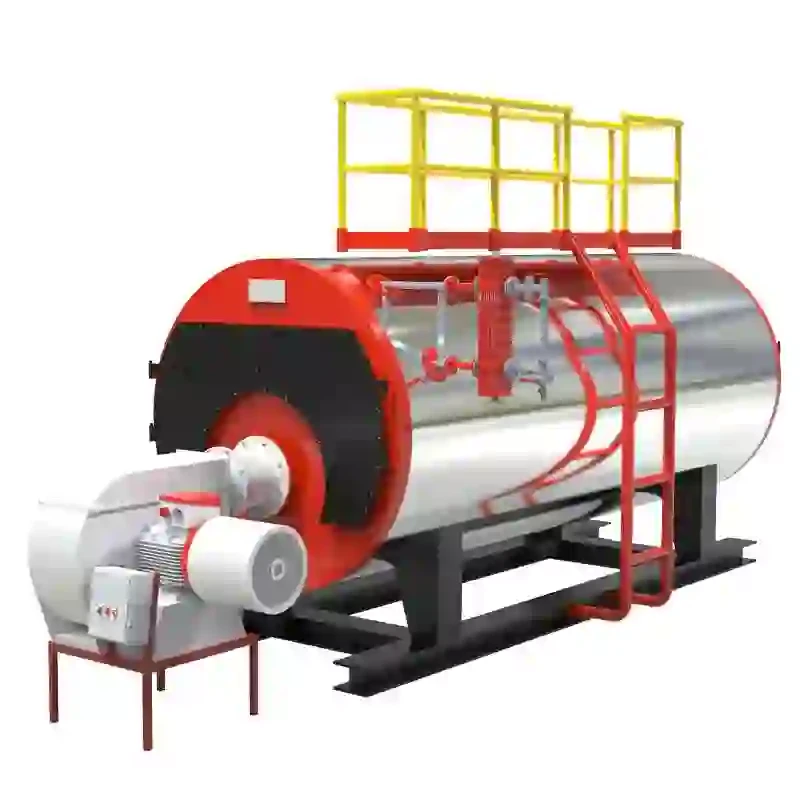
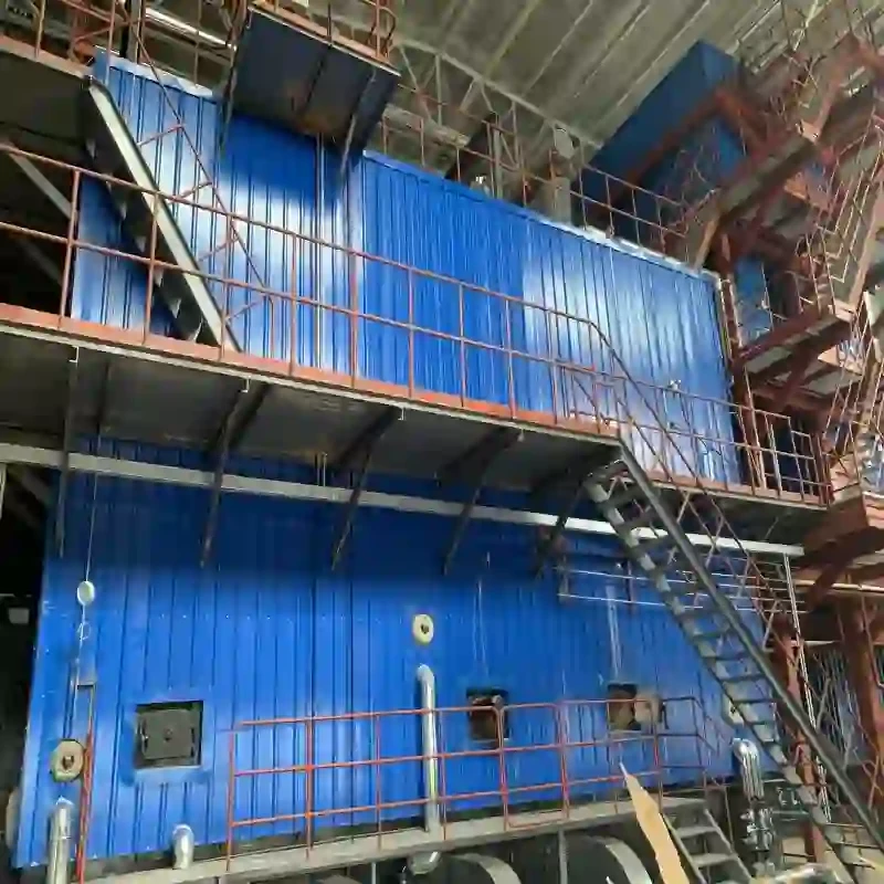
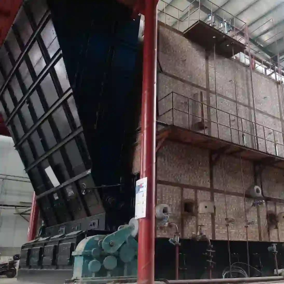
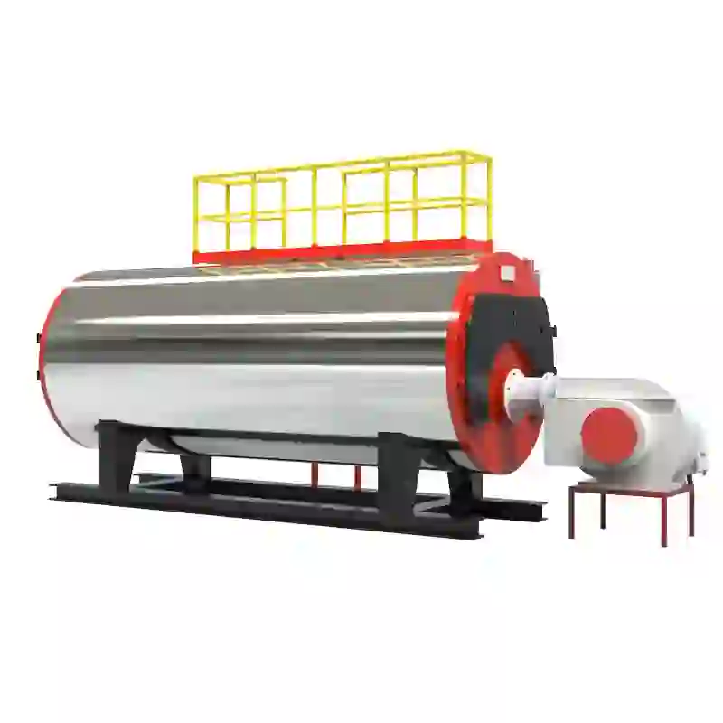
schematic diagram of steam boiler
Understanding the Schematic Diagram of a Steam Boiler
A steam boiler is a critical component in many industrial processes, providing the necessary heat and steam for various applications. To fully comprehend how steam boilers function, one must refer to their schematic diagrams, which serve as a visual guide to understanding the complex interrelationships of the components involved.
A typical steam boiler schematic diagram illustrates various parts, each with distinct functions tailored to the efficient production of steam. The primary elements depicted in these diagrams include the boiler body, burner, heat exchanger, feedwater system, steam outlet, and safety devices.
The boiler body is the central element of the unit, where water is heated to produce steam. It is typically made of high-quality steel that can withstand high pressures and temperatures. Within this body, the burner introduces fuel and air to initiate combustion. This combustion process generates heat, which raises the temperature of the water within the boiler.
The heat exchanger is another crucial component displayed in the schematic. It is designed to transfer heat generated by burning fuel to the water in the boiler without mixing the two. This is essential for the efficient production of steam, as it maximizes heat transfer while maintaining system safety.
schematic diagram of steam boiler

Water enters the system through the feedwater system, where it is pre-treated to remove impurities, ensuring that the steam produced is of high quality. The feedwater system often includes pumps that regulate water flow and control pressure, ensuring optimal performance.
From the boiler, steam is then transported through the steam outlet to various applications, such as turbines, heaters, or industrial processing equipment. The schematic also identifies piping pathways that guide the steam while maintaining the necessary pressure and temperature.
Safety is paramount in steam boiler operation, and this is reflected in the schematic. Safety devices such as pressure relief valves, water level indicators, and blow-off valves are depicted, ensuring that if the pressure exceeds safe levels or if water levels drop, the system can be safely managed to prevent accidents.
In addition to the components mentioned, a well-designed schematic will also include operational parameters and indicators for monitoring performance. This allows operators to make adjustments as needed, ensuring that the boiler operates efficiently and safely.
In conclusion, the schematic diagram of a steam boiler is an essential tool for understanding its functionality. Each component plays a vital role in the system, contributing to the overall efficiency and safety of steam production. Familiarity with these diagrams not only aids in operation but also in maintenance, ensuring that steam boilers continue to support industrial processes effectively.
-
High-Efficiency Commercial Oil Fired Steam Boiler for Industry
NewsJul.30,2025
-
High-Efficiency Biomass Fired Thermal Oil Boiler Solutions
NewsJul.30,2025
-
High Efficiency Gas Fired Thermal Oil Boiler for Industrial Heating
NewsJul.29,2025
-
High-Efficiency Gas Fired Hot Water Boiler for Sale – Reliable & Affordable
NewsJul.29,2025
-
High Efficiency Biomass Fired Hot Water Boiler for Industrial and Commercial Use
NewsJul.29,2025
-
High-Efficiency Biomass Fired Hot Water Boiler for Industrial Use
NewsJul.28,2025
Related PRODUCTS


