Jan . 30, 2025 03:34 Back to list
biomass fired steam boiler
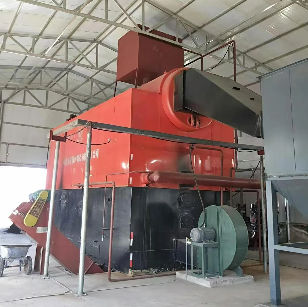
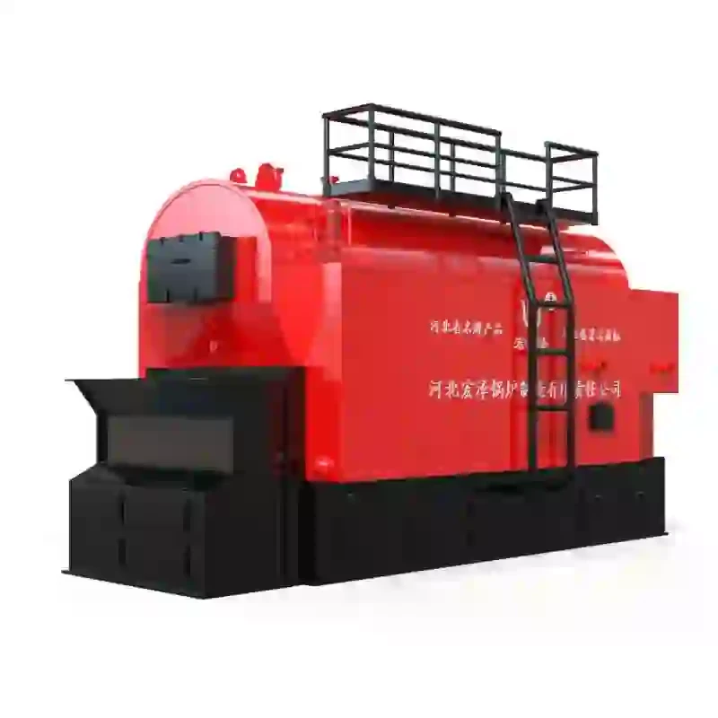
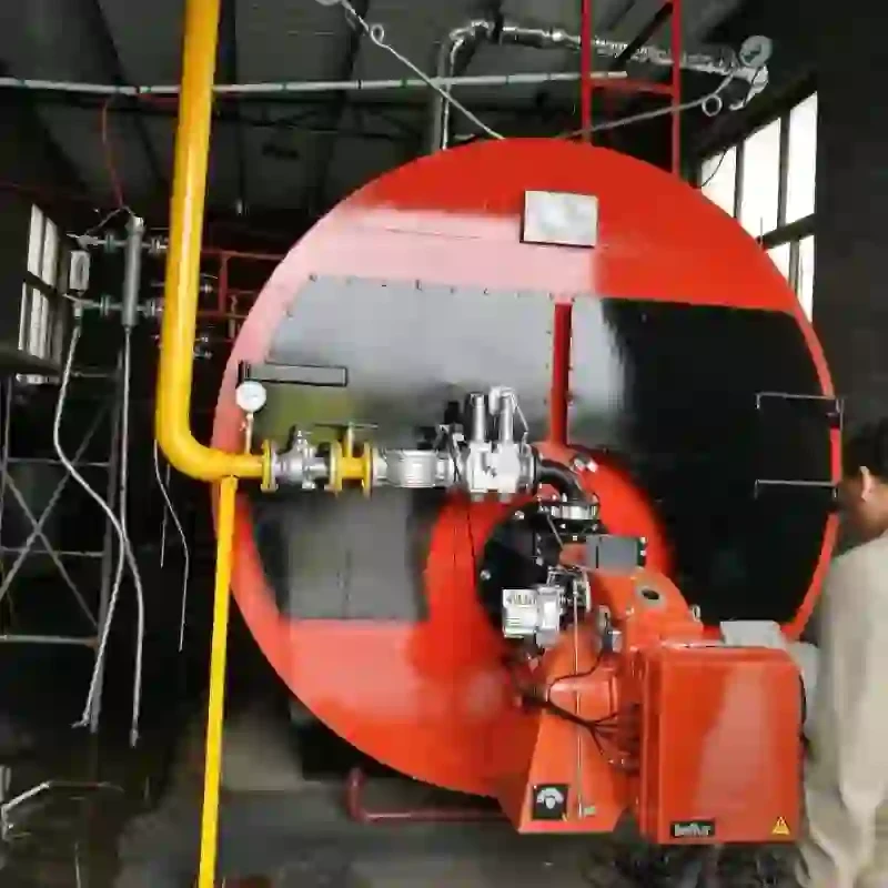
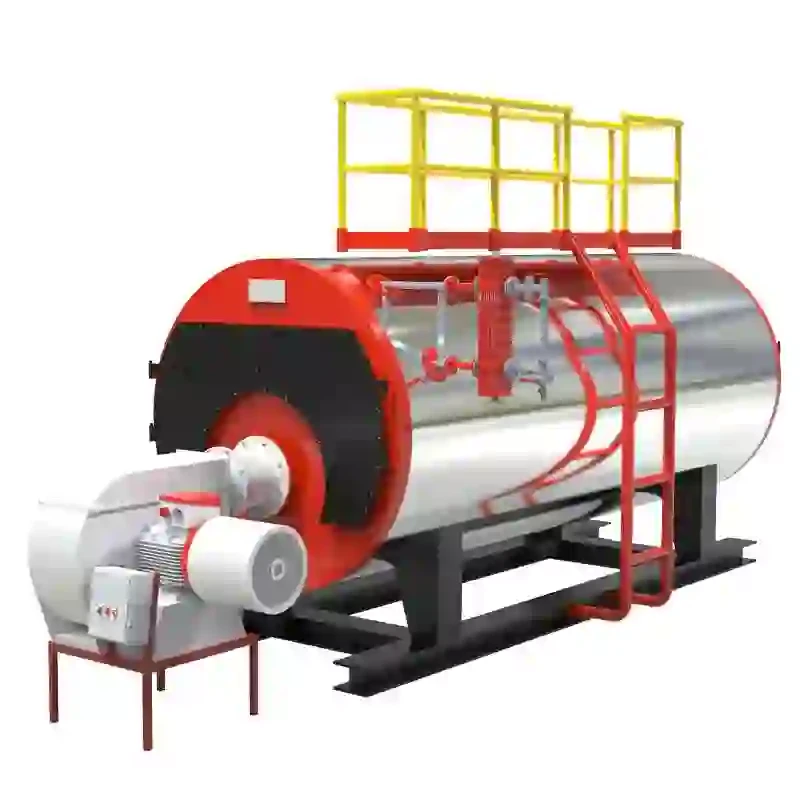
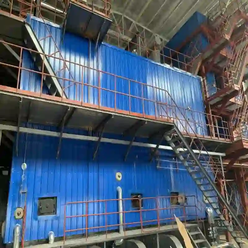
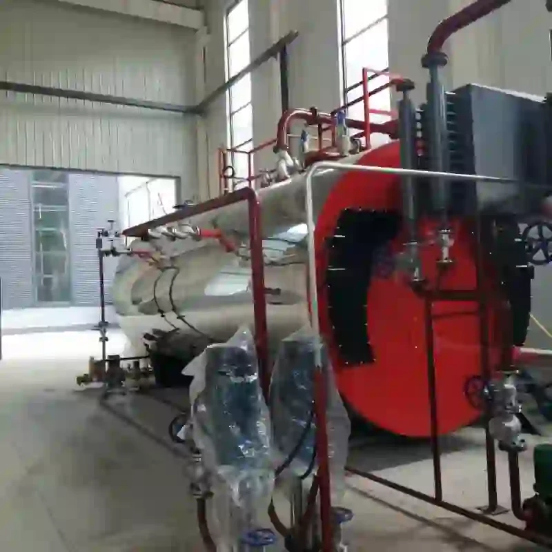
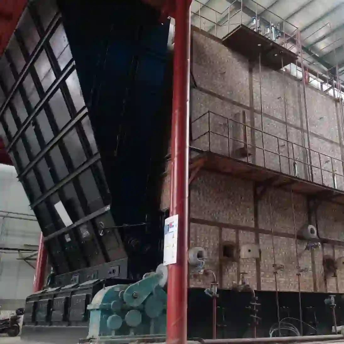
Understanding the intricacies of a simple steam boiler diagram requires a confluence of experience and technical expertise. A steam boiler, despite its simplicity, operates on precise scientific principles and is integral to various industrial processes, from generating electricity to providing heating solutions. Below is a comprehensive guide crafted to inform and assure readers of the technical robustness required to grasp these mechanical marvels.
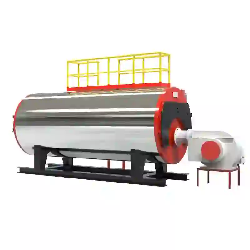
4. Steam Outlet The path through which steam exits to perform work. A detailed diagram will show the steam's journey from generation to exit, emphasizing pressure and temperature gauges along the route. Accurate monitoring of these gauges ensures the system operates within safe parameters. 5. Blowdown Valves Illustrated in diagrams, these valves play a role in removing sludge and sediment from the boiler, ensuring efficient heat transfer and prolonging the lifespan of the vessel. Their placement and operation are crucial for maintenance schedules and efficient boiler operation. 6. Safety Valves These components are paramount to a boiler's operation, preventing pressure from exceeding a dangerous threshold. In a diagram, safety valves are typically depicted prominently, underscoring their role in emergency scenarios. Authoritativeness and trust in a steam boiler diagram stem from the precision with which these components are represented and the clarity of their interactions. A reliable manufacturer or designer will always provide a detailed, standard-compliant diagram, offering insights into the boiler's operation and maintenance requirements. Purchasing boilers from established firms with proven expertise guarantees access to detailed and accurate diagrams, coupled with instructions and support. This enhances trust and assures users of the product's reliability and safety. In conclusion, a simple steam boiler diagram is an indispensable tool for understanding boiler operations. It provides essential insights into the interplay of its components, offering users and engineers the expertise needed for effective use and maintenance. Knowledge in this domain underscores a boiler's reliability and efficiency, reinforcing the importance of engaging with reputable manufacturers for high-quality products and guidance.

4. Steam Outlet The path through which steam exits to perform work. A detailed diagram will show the steam's journey from generation to exit, emphasizing pressure and temperature gauges along the route. Accurate monitoring of these gauges ensures the system operates within safe parameters. 5. Blowdown Valves Illustrated in diagrams, these valves play a role in removing sludge and sediment from the boiler, ensuring efficient heat transfer and prolonging the lifespan of the vessel. Their placement and operation are crucial for maintenance schedules and efficient boiler operation. 6. Safety Valves These components are paramount to a boiler's operation, preventing pressure from exceeding a dangerous threshold. In a diagram, safety valves are typically depicted prominently, underscoring their role in emergency scenarios. Authoritativeness and trust in a steam boiler diagram stem from the precision with which these components are represented and the clarity of their interactions. A reliable manufacturer or designer will always provide a detailed, standard-compliant diagram, offering insights into the boiler's operation and maintenance requirements. Purchasing boilers from established firms with proven expertise guarantees access to detailed and accurate diagrams, coupled with instructions and support. This enhances trust and assures users of the product's reliability and safety. In conclusion, a simple steam boiler diagram is an indispensable tool for understanding boiler operations. It provides essential insights into the interplay of its components, offering users and engineers the expertise needed for effective use and maintenance. Knowledge in this domain underscores a boiler's reliability and efficiency, reinforcing the importance of engaging with reputable manufacturers for high-quality products and guidance.
Share
Latest News
-
Efficient Biomass Fired Hot Water Boiler | AI Heating Solution
NewsAug.01,2025
-
High-Efficiency Gas Thermal Oil Boilers | HPT Models
NewsJul.31,2025
-
Oil Fired Hot Water Boilers Sale - High Efficiency & Affordable
NewsJul.31,2025
-
High-Efficiency Commercial Oil Fired Steam Boiler for Industry
NewsJul.30,2025
-
High-Efficiency Biomass Fired Thermal Oil Boiler Solutions
NewsJul.30,2025
-
High Efficiency Gas Fired Thermal Oil Boiler for Industrial Heating
NewsJul.29,2025
Related PRODUCTS
Copyright © 2025 HEBEI HONGZE BOILER MANUFACTURING CO., LTD. All Rights Reserved. Sitemap | Privacy Policy


