Sep . 14, 2024 22:06 Back to list
steam boiler electrical diagram
Understanding the Electrical Diagram of a Steam Boiler
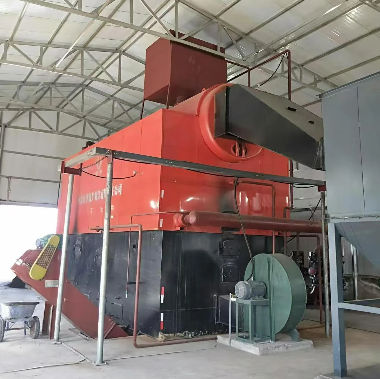
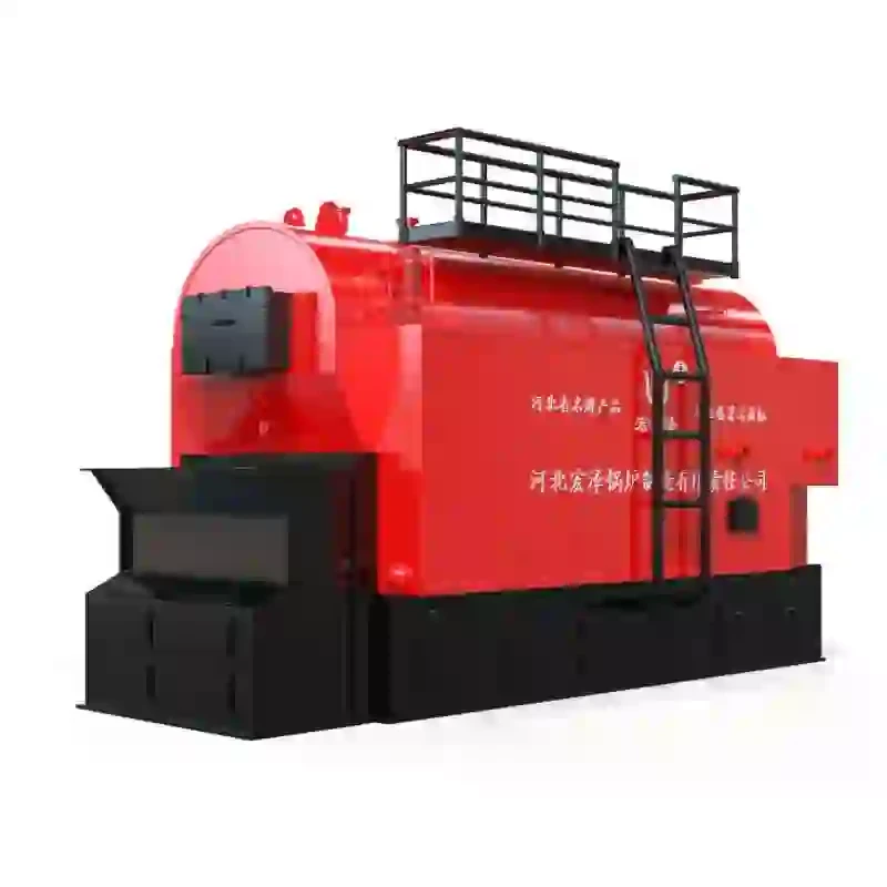
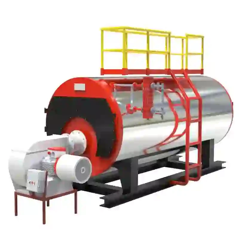
Steam boilers play a crucial role in various industrial processes, providing essential heat and power. A clear understanding of their electrical diagrams is vital for engineers, technicians, and maintenance personnel who work with these systems. This article delves into the components and functionalities outlined in a typical steam boiler electrical diagram, emphasizing its significance in ensuring safe and efficient operation.
At its core, an electrical diagram for a steam boiler illustrates how various electrical components are interconnected. These components typically include the boiler controls, safety systems, sensors, and power supply units. The diagram acts as a blueprint, allowing technicians to comprehend the flow of electricity and the sequence of operations that ensure the boiler functions correctly.
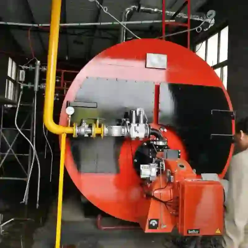
One of the primary components depicted in an electrical diagram is the boiler control panel. This panel houses various switches, indicators, and controllers that manage the boiler's operation. The control system usually consists of a Programmable Logic Controller (PLC) or a dedicated control unit that regulates parameters such as pressure, temperature, and water levels. The control panel also interfaces with safety systems, ensuring that the boiler operates within specified parameters to prevent hazardous situations.
Safety is a top priority in steam boiler operation, and electrical diagrams illustrate several safety mechanisms. These may include pressure relief valves, low water cut-off switches, and emergency stop buttons. For example, the low water cut-off switch is critical in preventing boiler damage; if the water level drops below a safe threshold, this switch automatically interrupts the power supply to the burner, thereby halting combustion.
steam boiler electrical diagram

Another essential element in the electrical diagram is the sensors and instrumentation. Pressure and temperature sensors provide real-time data to the control system, allowing it to make necessary adjustments. Flow meters and level sensors are also crucial for monitoring the system's performance and ensuring that water and steam are circulating appropriately.
The power supply to the boiler is another critical aspect depicted in the electrical diagram. It includes transformers, circuit breakers, and wiring systems that deliver electricity to various components. Understanding the power supply configuration is essential for troubleshooting, as any disruption in the power supply can lead to boiler malfunction or, in worst-case scenarios, accidents.
Moreover, the diagram helps personnel identify potential issues by tracing the connections and functions of each component. For instance, if a boiler fails to ignite, technicians can refer to the electrical diagram to check the control signals, power supply integrity, and the condition of safety devices.
In conclusion, understanding the electrical diagram of a steam boiler is paramount for ensuring its efficient and safe operation. By familiarizing oneself with the various components and their interplay, engineers and technicians can enhance their troubleshooting skills and maintain the operational integrity of the steam boiler. As industries increasingly rely on steam boilers for their processes, mastering these diagrams becomes an essential part of modern engineering practices. Proper training and adherence to these diagrams ultimately contribute to safer work environments and more efficient industrial operations.
-
High-Efficiency Commercial Oil Fired Steam Boiler for Industry
NewsJul.30,2025
-
High-Efficiency Biomass Fired Thermal Oil Boiler Solutions
NewsJul.30,2025
-
High Efficiency Gas Fired Thermal Oil Boiler for Industrial Heating
NewsJul.29,2025
-
High-Efficiency Gas Fired Hot Water Boiler for Sale – Reliable & Affordable
NewsJul.29,2025
-
High Efficiency Biomass Fired Hot Water Boiler for Industrial and Commercial Use
NewsJul.29,2025
-
High-Efficiency Biomass Fired Hot Water Boiler for Industrial Use
NewsJul.28,2025
Related PRODUCTS


