Sep . 19, 2024 06:05 Back to list
steam boiler installation diagram
Understanding Steam Boiler Installation Diagrams
Steam boiler installation diagrams are essential tools in the design and implementation of steam heating systems. These diagrams provide a visual representation of how the various components of a steam boiler system are arranged and interconnected. Whether for industrial, commercial, or residential applications, understanding these diagrams is crucial for engineers, technicians, and maintenance personnel involved in the installation and operation of steam boilers.
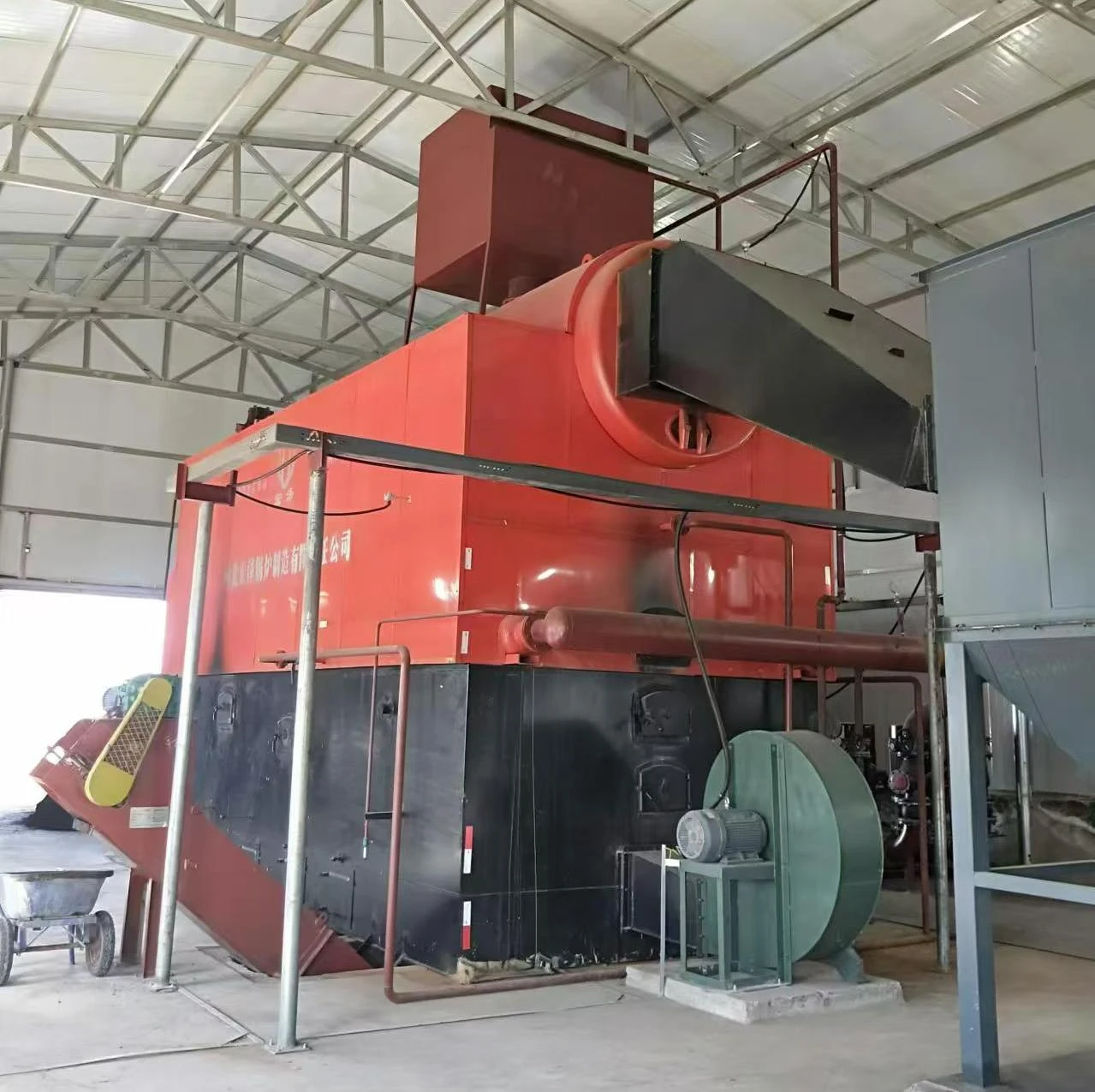
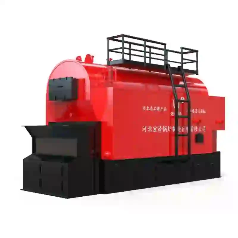
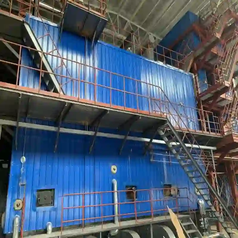
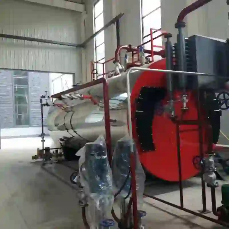
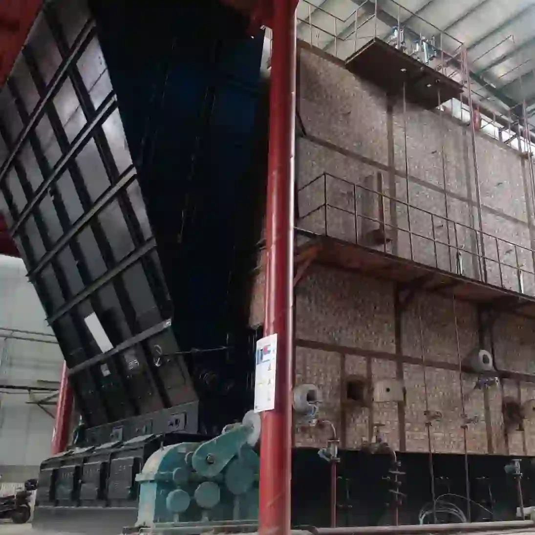
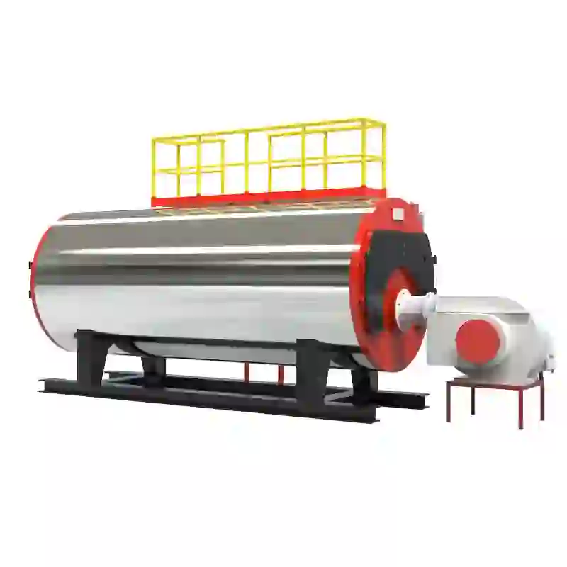
At the heart of a steam boiler system is the boiler itself, which serves as a vessel for heating water to generate steam. The installation diagram typically outlines the main components, including the boiler, feedwater system, steam output, flue gas lines, and safety devices. It provides a clear map of where each component is situated and how they interact within the system.
Key Components of Steam Boiler Installation Diagrams
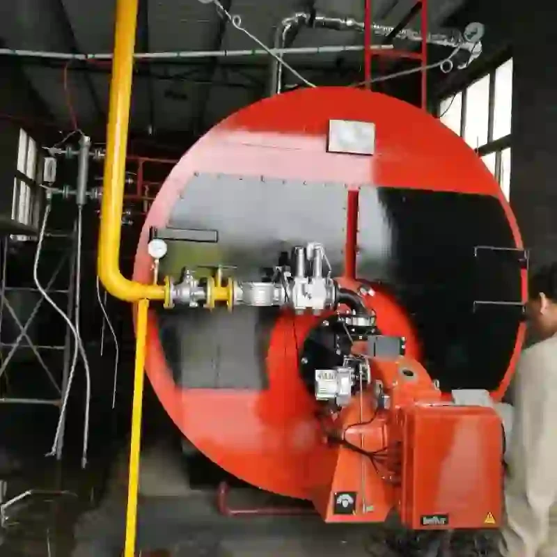
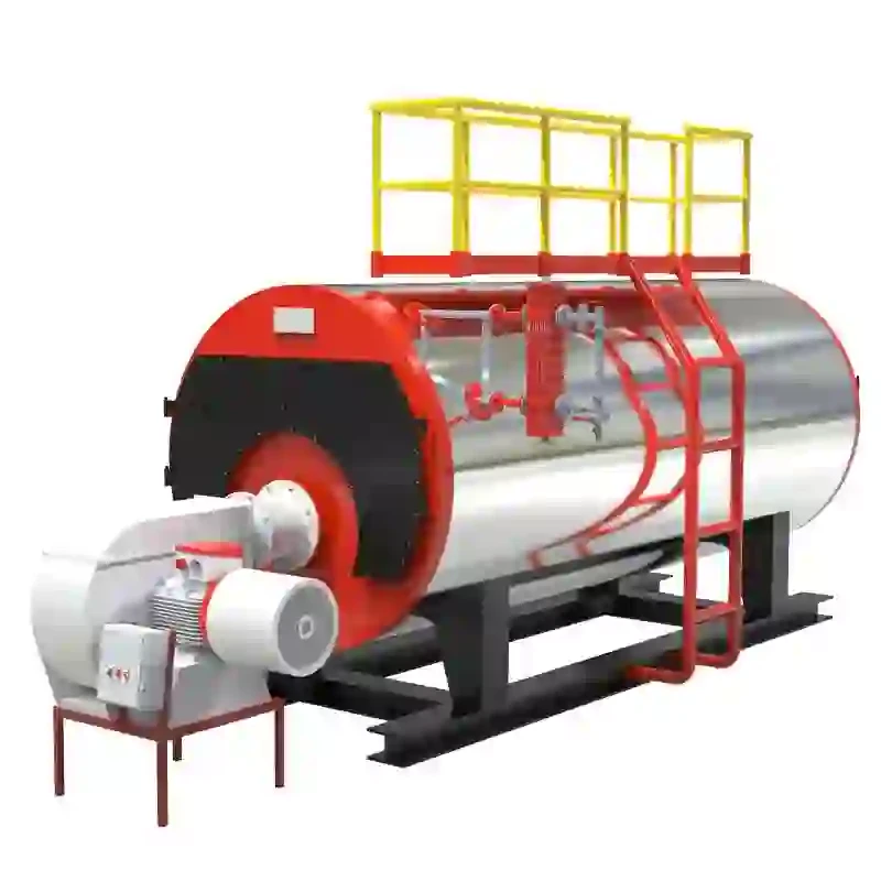
1. Boiler This is the focal point of the diagram. It is shown along with its essential features, such as the burner, combustion chamber, and heat exchanger. The capacity and type of boiler (such as fire-tube or water-tube) can also affect the layout.
2. Feedwater System This system is responsible for supplying water to the boiler. The installation diagram illustrates how the feedwater is piped into the boiler, often featuring components like feedwater pumps, valves, and flowmeters.
3. Steam Distribution Once steam is generated, it needs to be distributed effectively. The diagram typically shows the piping that carries steam from the boiler to various points of use, which could be heating coils, turbines, or other applications.
steam boiler installation diagram

4. Flue Gas System As the boiler burns fuel, it produces flue gases that must be vented outside. The installation diagram will outline the flue gas path and its connection to the chimney or flue stack, including any associated components like economizers or air preheaters.
5. Safety Devices Safety is paramount in any steam system. The diagram will include various safety devices such as pressure relief valves, water level indicators, and appropriate controls to monitor and manage the system’s operation.
Importance of Proper Installation
A well-designed installation diagram not only aids in the physical assembly of the system but also facilitates troubleshooting and maintenance. Proper layout ensures efficient operation, minimizes energy loss, and enhances the safety of the steam system. Understanding these diagrams allows technicians to identify potential issues, such as inadequate piping size or improper component placement, which can lead to operational inefficiencies or even hazardous conditions.
Conclusion
In summary, steam boiler installation diagrams are indispensable tools that provide a comprehensive view of an entire steam heating system. They help ensure that all components are correctly installed and configured for optimal performance. For anyone involved in the design, installation, or maintenance of steam boilers, familiarity with these diagrams is critical. By following the guidelines laid out in the installation diagram, engineers and technicians can create safe, efficient, and reliable steam heating systems that meet the demands of modern applications. Whether in a factory or a residential setting, the principles of steam boiler installation remain vital for successful energy management and system operation.
-
High-Efficiency Commercial Oil Fired Steam Boiler for Industry
NewsJul.30,2025
-
High-Efficiency Biomass Fired Thermal Oil Boiler Solutions
NewsJul.30,2025
-
High Efficiency Gas Fired Thermal Oil Boiler for Industrial Heating
NewsJul.29,2025
-
High-Efficiency Gas Fired Hot Water Boiler for Sale – Reliable & Affordable
NewsJul.29,2025
-
High Efficiency Biomass Fired Hot Water Boiler for Industrial and Commercial Use
NewsJul.29,2025
-
High-Efficiency Biomass Fired Hot Water Boiler for Industrial Use
NewsJul.28,2025
Related PRODUCTS


