Sep . 04, 2024 15:03 Back to list
steam boiler schematic diagram
Understanding Steam Boiler Schematic Diagrams
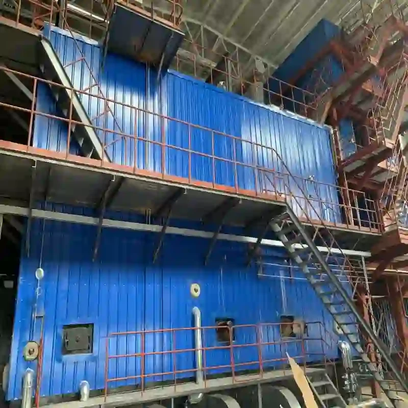
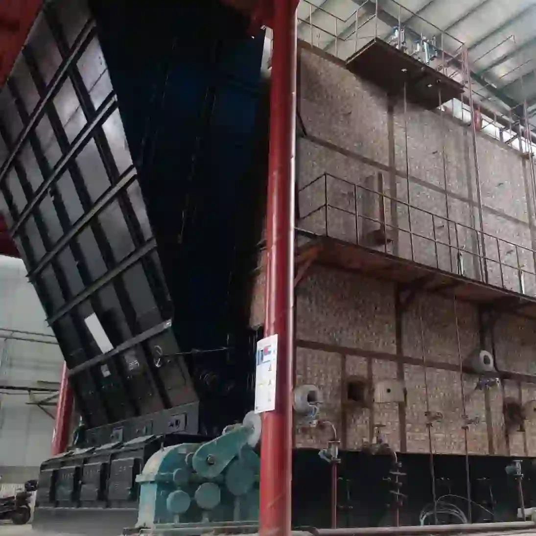
A steam boiler is a crucial component in various industries, providing steam for heating and processing needs. To effectively operate and maintain a steam boiler, it is essential to understand its schematic diagram, which visually represents the system's components and their interconnections. This article will delve into the fundamental elements of steam boiler schematic diagrams, their significance, and the general operation of a steam boiler.
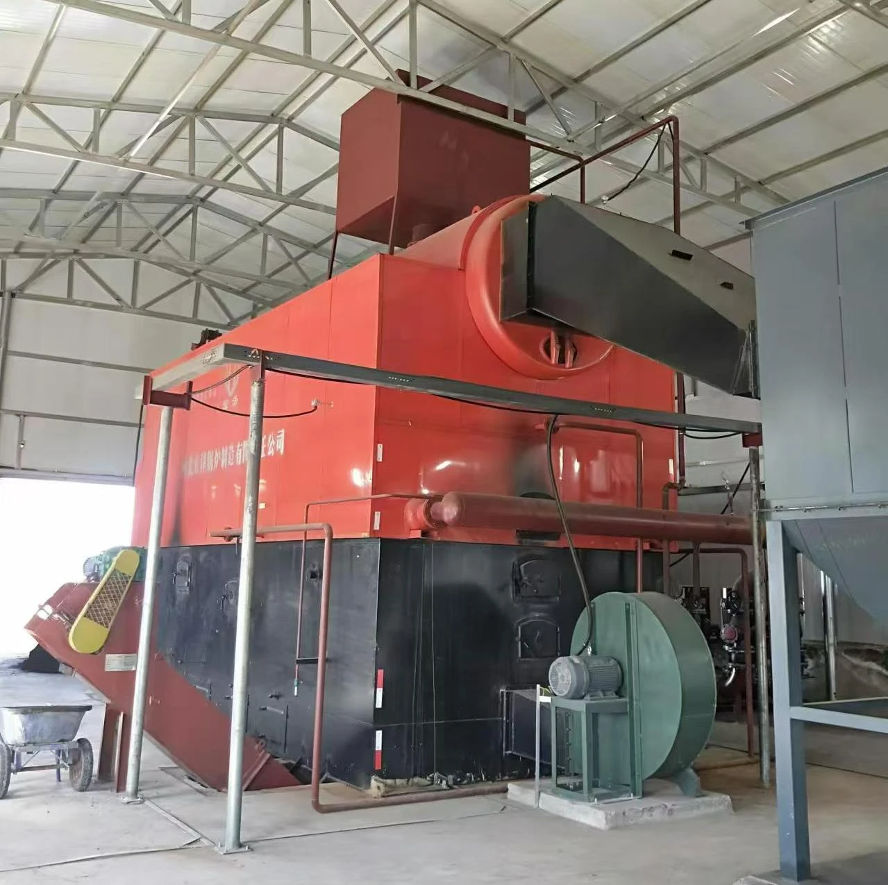
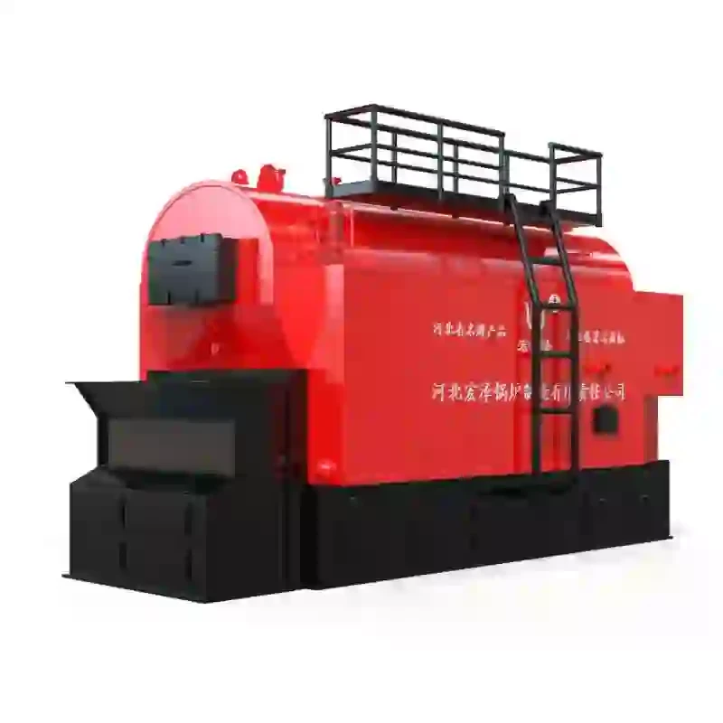
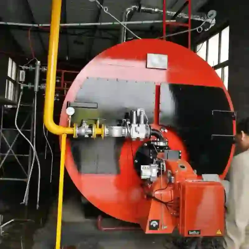
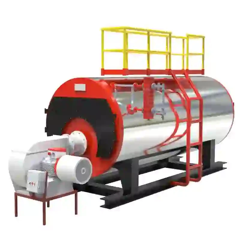
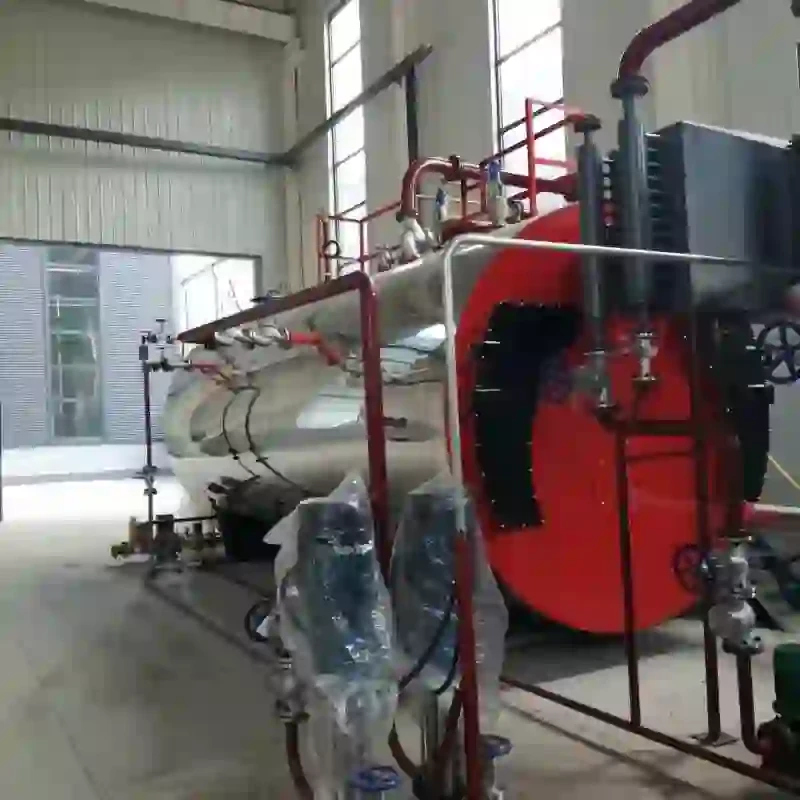
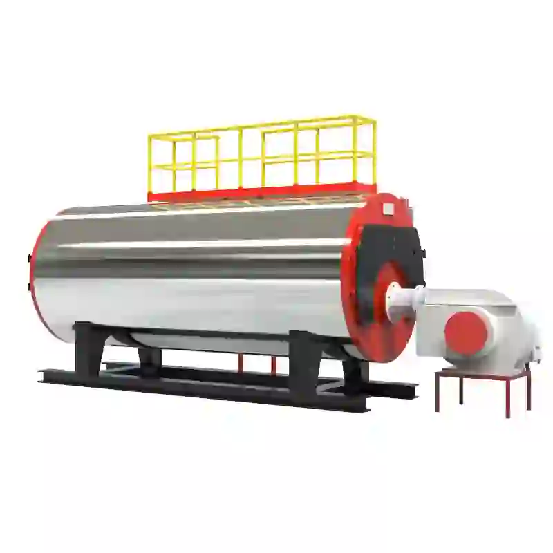
A typical steam boiler schematic diagram comprises several key components, including the boiler shell, furnace, burner, heat exchanger, water feed system, blowdown system, pressure relief valves, and various piping connections
. Each component plays a critical role in the overall functioning of the boiler.The boiler shell is the outer casing that contains water and steam. Inside this shell, the furnace is where the burning of fuel occurs, generating heat. The burner introduces fuel into the furnace, which can be natural gas, oil, or even biomass, depending on the design and application of the boiler. The heat generated in the furnace heats the water in the boiler shell, producing steam.
The schematic also includes the water feed system, which ensures that the boiler maintains proper water levels. This system typically consists of a feedwater pump and various valves to control the flow of water into the boiler. Maintaining the right water level is critical, as low water levels can lead to overheating and potential damage to the boiler.
steam boiler schematic diagram

Another vital aspect of the steam boiler schematic is the blowdown system. This system is responsible for removing impurities and sediments that accumulate in the boiler water. Regular blowdown helps maintain water quality and prevent scale buildup, which can reduce efficiency and lead to operational issues.
Pressure relief valves are essential for safety, allowing excess steam pressure to escape the boiler. This prevents dangerous situations, such as explosions or structural failures, ensuring the system operates within safe limits.
Understanding the flow of steam and water within the boiler is also critical. The diagram typically shows the steam outlet connected to the piping system that delivers steam to various points of use, such as turbines, heaters, or process equipment. Additionally, the return line sends condensate back to the boiler for reuse, enhancing efficiency through water recycling.
In summary, steam boiler schematic diagrams are invaluable tools for engineers, operators, and maintenance personnel. They provide a clear and concise representation of the boiler's structure and function, facilitating troubleshooting and maintenance tasks. A solid grasp of the components and their relationships within the schematic enhances safety, operational efficiency, and longevity of the steam boiler system. Understanding these diagrams not only promotes better operational practices but also contributes to effective training for new personnel entering the field, ensuring that steam boilers serve their critical role in industrial processes efficiently and safely.
-
High-Efficiency Commercial Oil Fired Steam Boiler for Industry
NewsJul.30,2025
-
High-Efficiency Biomass Fired Thermal Oil Boiler Solutions
NewsJul.30,2025
-
High Efficiency Gas Fired Thermal Oil Boiler for Industrial Heating
NewsJul.29,2025
-
High-Efficiency Gas Fired Hot Water Boiler for Sale – Reliable & Affordable
NewsJul.29,2025
-
High Efficiency Biomass Fired Hot Water Boiler for Industrial and Commercial Use
NewsJul.29,2025
-
High-Efficiency Biomass Fired Hot Water Boiler for Industrial Use
NewsJul.28,2025
Related PRODUCTS


