Sep . 02, 2024 15:01 Back to list
Steam Boiler System
Understanding the Steam Boiler System Diagram
Steam boiler systems play a crucial role in various industries, providing the necessary steam for heating, power generation, and other applications
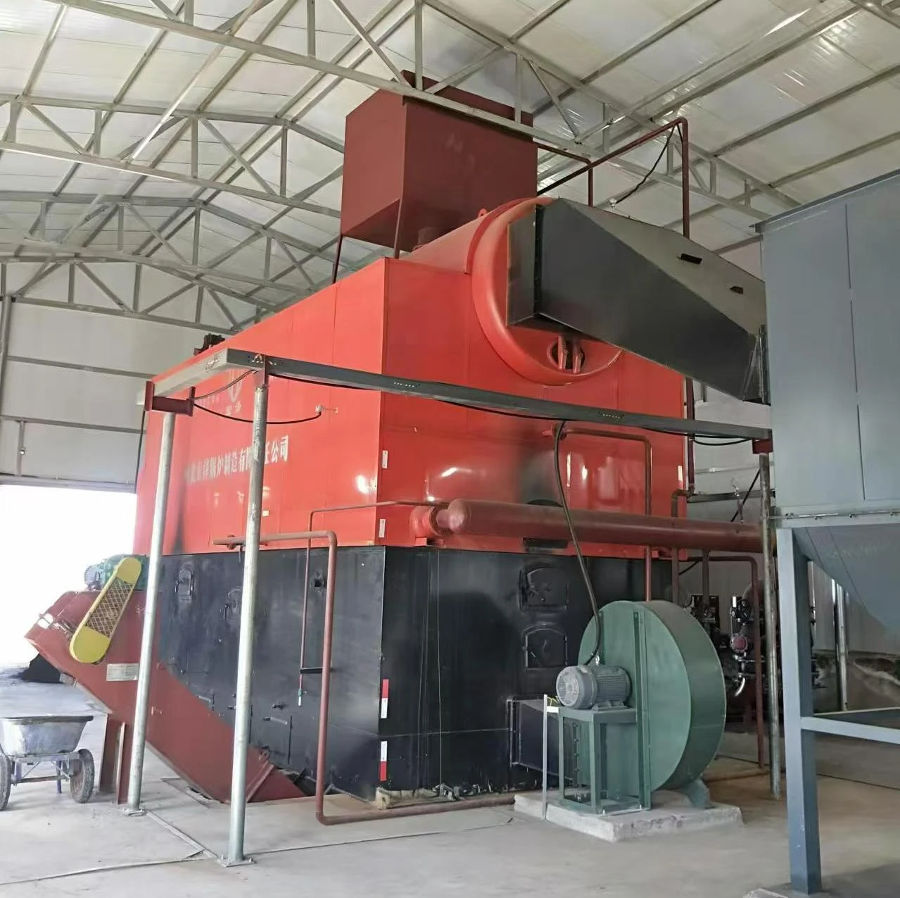
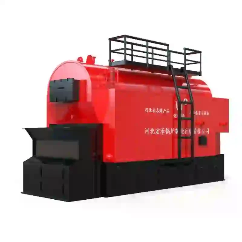
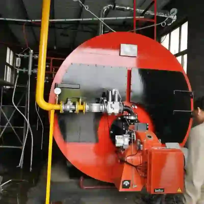
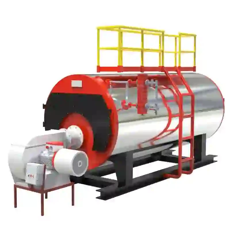
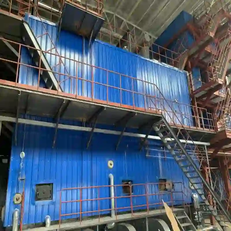
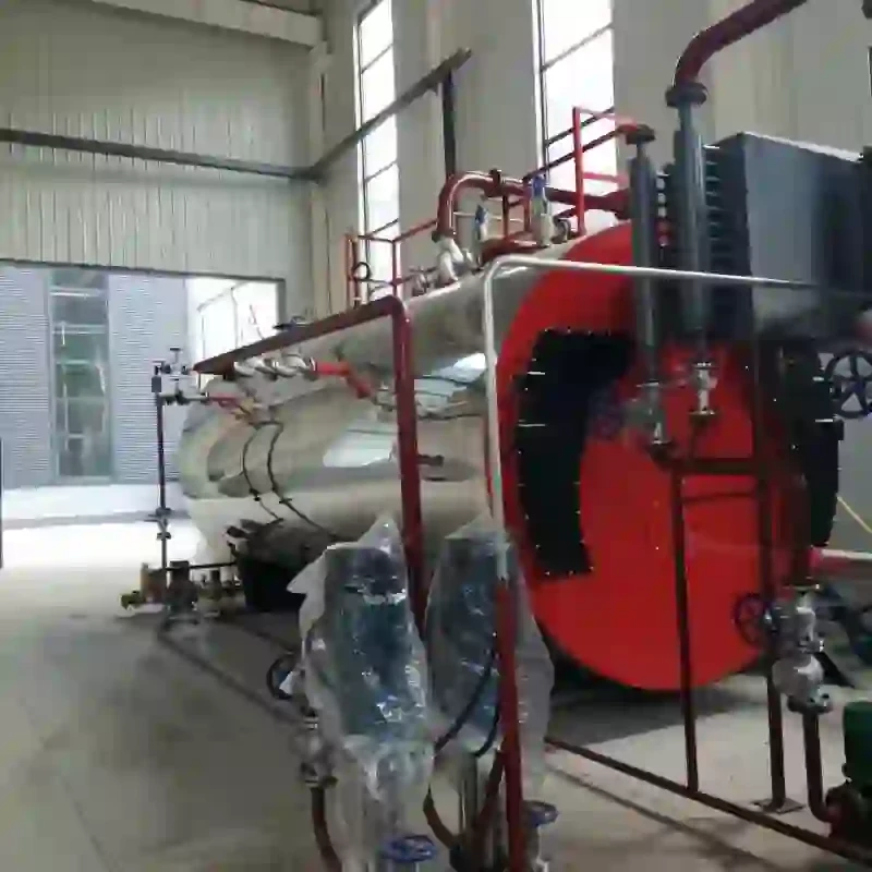
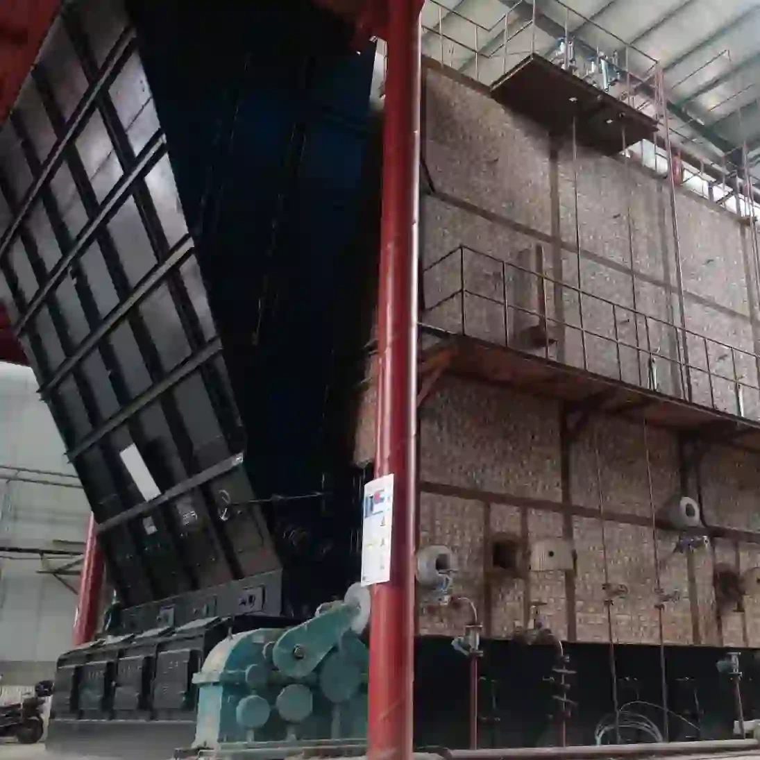
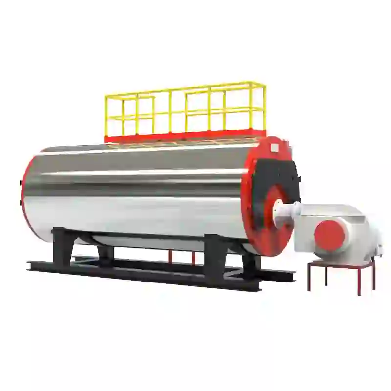
. A steam boiler system diagram serves as a visual representation of the components involved in the operation of a steam boiler, illustrating how these components interact to produce steam efficiently.At the heart of a steam boiler system is the boiler itself, which is designed to convert water into steam through the application of heat. The fuel source, whether it be natural gas, oil, coal, or biomass, is burned in the combustion chamber, generating heat. The boiler diagram typically showcases the furnace, where the burning process occurs, and the heat exchanger, which transfers the generated heat to the water.
One of the significant components delineated in a steam boiler system diagram is the feedwater system. This system is responsible for supplying water to the boiler. It includes a feedwater pump that takes water from a storage tank or the main water supply and delivers it to the boiler. The diagram often highlights various valves and controls that ensure the correct pressure and flow of water into the boiler, preventing potential damage from inadequate water levels.
steam boiler system diagram
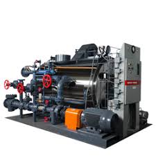
The steam generation process is depicted by the steam drum and the associated piping system. Once the water in the boiler reaches the desired temperature and pressure, it is converted into steam. The steam drum acts as a reservoir for the generated steam, allowing it to accumulate before being transported through the piping to its intended destination. The diagram illustrates safety components such as pressure relief valves, which are vital in preventing excessive pressure buildup that could lead to dangerous failures.
Another essential aspect of a steam boiler system is the condensate return system. After steam has done its work, it condenses back into water. The condensate return system collects this condensate and pumps it back to the feedwater system, thus creating a closed loop that enhances energy efficiency. The diagram commonly shows condensate pumps and heat exchangers that reclaim energy from the condensate before it is returned to the boiler, further reducing fuel consumption.
To maintain efficiency and ensure safe operation, the steam boiler system also includes monitoring and control systems. These often consist of various sensors that measure parameters like pressure, temperature, and water levels. The boiler diagram may incorporate control panels where operators can oversee these systems and make adjustments as necessary.
In conclusion, a steam boiler system diagram is an informative tool that simplifies the understanding of the various components and their functions within a steam boiler system. By illustrating the flow of energy, water, and steam, these diagrams help engineers and operators troubleshoot issues, optimize performance, and ensure the safe, reliable operation of steam boilers in countless industrial applications. Understanding this diagram is essential for anyone involved in the design, operation, or maintenance of steam boiler systems.
-
High-Efficiency Commercial Oil Fired Steam Boiler for Industry
NewsJul.30,2025
-
High-Efficiency Biomass Fired Thermal Oil Boiler Solutions
NewsJul.30,2025
-
High Efficiency Gas Fired Thermal Oil Boiler for Industrial Heating
NewsJul.29,2025
-
High-Efficiency Gas Fired Hot Water Boiler for Sale – Reliable & Affordable
NewsJul.29,2025
-
High Efficiency Biomass Fired Hot Water Boiler for Industrial and Commercial Use
NewsJul.29,2025
-
High-Efficiency Biomass Fired Hot Water Boiler for Industrial Use
NewsJul.28,2025
Related PRODUCTS


