Dec . 11, 2024 10:30 Back to list
Steam Boiler Control Wiring Diagram for Efficient Operation and Safety Management Systems
Understanding Steam Boiler Control Wiring Diagrams
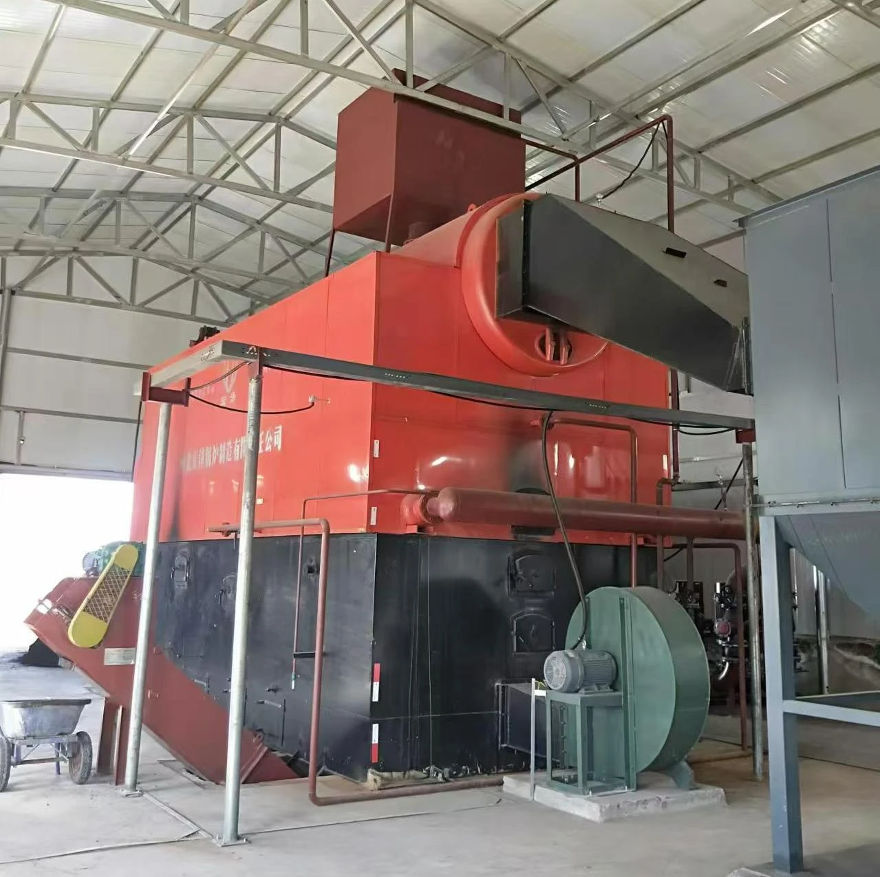
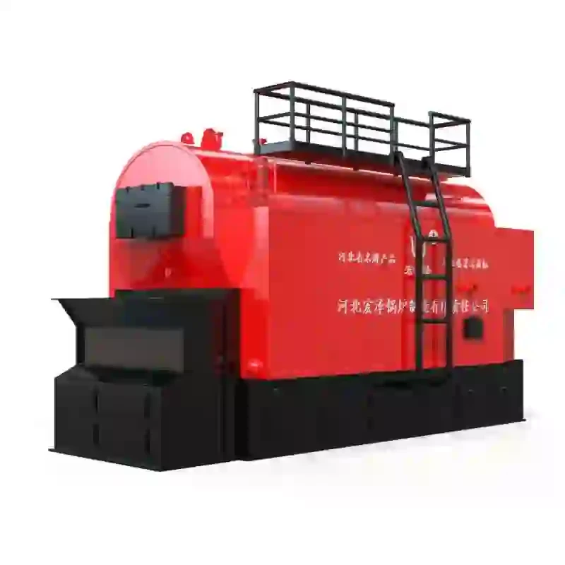
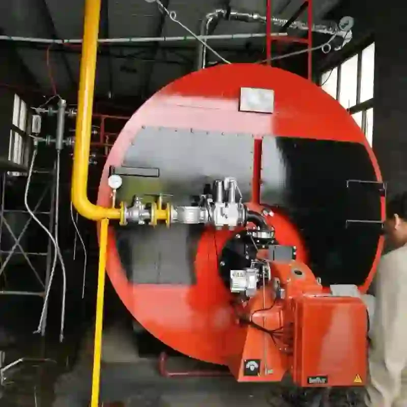
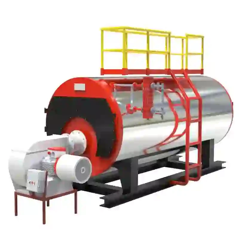
Steam boilers are essential components in various industrial applications, providing steam for heating, power generation, and various processes. Understanding the control wiring of a steam boiler is crucial for safe and efficient operation. Control wiring diagrams serve as a blueprint for understanding how the different components of a steam boiler system interact. This article will explore the significance of steam boiler control wiring diagrams, their components, and their relevance in troubleshooting and maintaining boiler operations.
Importance of Control Wiring Diagrams
Control wiring diagrams are vital for technicians and engineers when installing, maintaining, or troubleshooting steam boiler systems. They represent the electrical connections between various components, such as safety devices, controls, and indicators. These diagrams help visualize the layout and connections, ensuring that technicians understand how to wire and operate the system properly.
Without a proper understanding of these diagrams, technicians may encounter difficulties in identifying faults or making necessary adjustments. Hence, control wiring diagrams reduce the risk of errors during maintenance and ensure compliance with safety standards.
Components of a Steam Boiler Control Wiring Diagram
A typical steam boiler control wiring diagram includes various elements, each performing a specific function. Here are some key components that are often highlighted
1. Boiler Control Panel This is the centralized unit where operators can monitor and manage the boiler’s operation. It includes control switches, indicators, and sometimes a digital display for reading pressure and temperature.
2. Safety Devices Safety is paramount in boiler operation. Safety devices such as pressure switches, temperature sensors, and low-water cutoff switches are incorporated into the wiring diagram. These components are crucial for preventing accidents by shutting down the boiler if unsafe conditions arise.
3. Power Supply The diagram will also outline how the system is powered, including the main electrical supply lines and safety disconnect switches. Proper power supply is essential to ensure all components function effectively.
4. Valves and Dampers The control wiring for the valves and dampers is essential for regulating and controlling steam flow and air intake. They are often motorized and include limit switches for feedback to the control panel.
steam boiler control wiring diagram

5. Actuators and Relays Actuators are used to control the mechanical movements of the boiler system. Relays facilitate control signals, enabling the safe functioning of high voltage components through low voltage signals.
6. Alarm Systems An effective boiler control wiring diagram will incorporate alarm systems that alert personnel to faults or anomalies within the system. These alarms can include audible signals, as well as visual indicators on the control panel.
Reading a Control Wiring Diagram
To effectively read a steam boiler control wiring diagram, one must familiarize themselves with standard electrical symbols and nomenclature used in diagrams. Typically, each component is represented by a unique symbol, along with numbers or letters indicating its function or connection points.
When interpreting the diagram, follow the circuit lines to trace connections between components. It is essential to understand the flow of electricity and how each component interacts within the system. Additionally, taking note of the color codes for wiring can be beneficial, as different colors often denote the function of the wires, such as live, neutral, or ground.
Troubleshooting Using Control Wiring Diagrams
When issues arise within a steam boiler system, control wiring diagrams prove invaluable for troubleshooting. Technicians can refer to the provided diagrams to identify the failed component and the nature of the failure. For instance, if a safety device is not functioning, the diagram will help pinpoint whether the issue lies in the device itself, the wiring, or connections to the control panel.
Moreover, these diagrams facilitate systematic testing of components. By understanding the wiring layout, technicians can isolate sections of the circuit to determine where a fault exists, thereby minimizing downtime and ensuring swift repairs.
Conclusion
Steam boiler control wiring diagrams are a crucial tool in the effective management of boiler systems. They provide a clear outline of wiring connections, enhance safety, and improve troubleshooting efficiency. Whether for installation, maintenance, or emergency repairs, understanding these diagrams allows technicians to maintain efficient operations and minimize risks associated with steam boiler systems. As technology advances and boiler systems become more intricate, the role of detailed control wiring diagrams will only continue to grow in importance.
-
High-Efficiency Commercial Oil Fired Steam Boiler for Industry
NewsJul.30,2025
-
High-Efficiency Biomass Fired Thermal Oil Boiler Solutions
NewsJul.30,2025
-
High Efficiency Gas Fired Thermal Oil Boiler for Industrial Heating
NewsJul.29,2025
-
High-Efficiency Gas Fired Hot Water Boiler for Sale – Reliable & Affordable
NewsJul.29,2025
-
High Efficiency Biomass Fired Hot Water Boiler for Industrial and Commercial Use
NewsJul.29,2025
-
High-Efficiency Biomass Fired Hot Water Boiler for Industrial Use
NewsJul.28,2025
Related PRODUCTS


