Sep . 21, 2024 18:45 Back to list
steam boiler diagram pdf
An Overview of Steam Boiler Diagrams
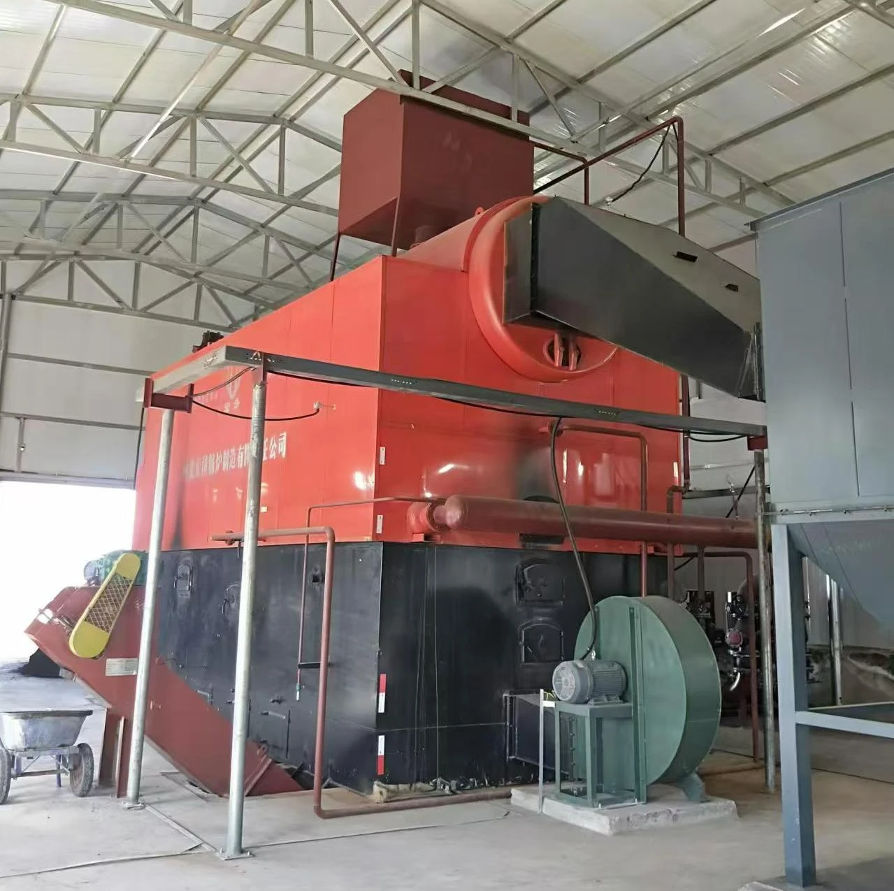
Steam boilers are integral components in various industrial applications, from generating power to heating processes. Understanding the diagram of a steam boiler is essential for engineers and technicians involved in the maintenance and operation of these systems. A typical steam boiler diagram illustrates the essential parts and their functions, making it easier to grasp how steam generation works.
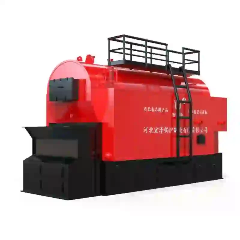
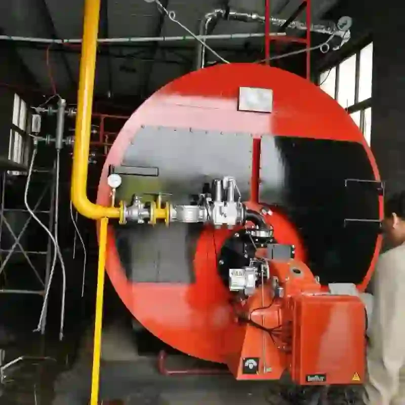
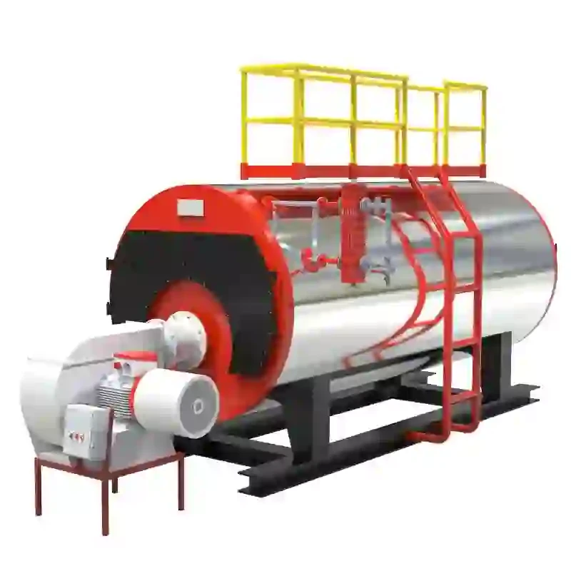
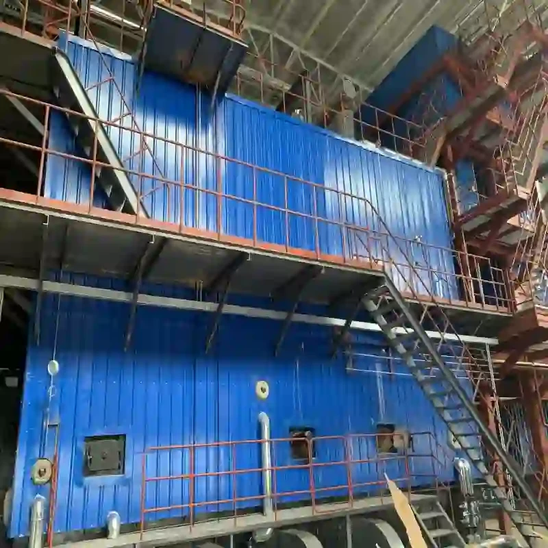
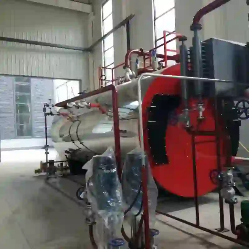
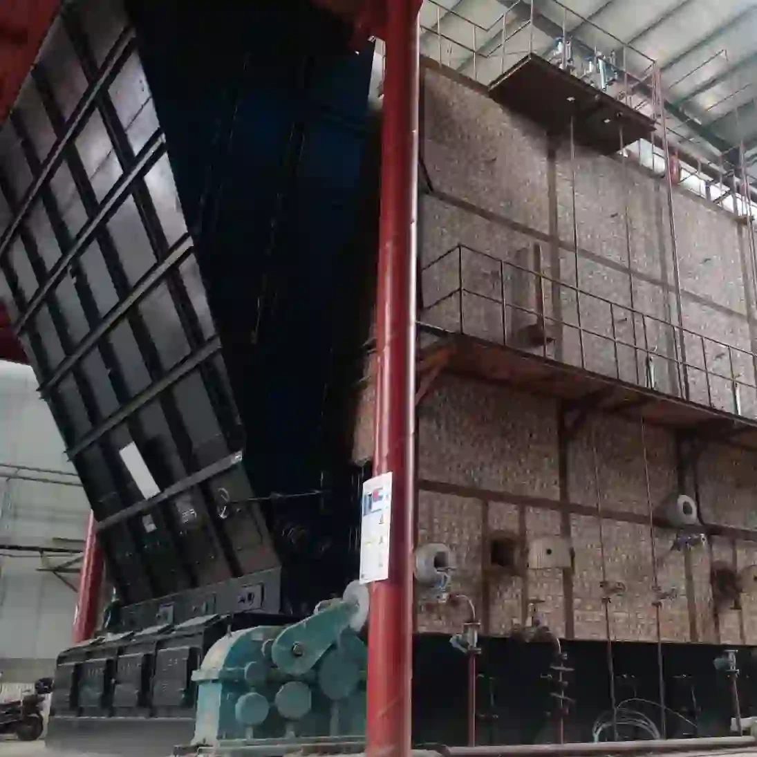
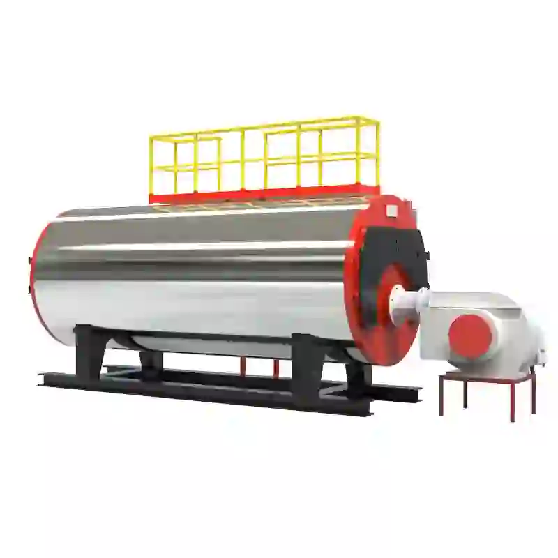
At its core, a steam boiler operates on the principle of converting water into steam through the application of heat. The diagram usually starts with a representation of the boiler itself, which can vary in design—from fire-tube boilers to water-tube boilers, each suited for specific applications.
An Overview of Steam Boiler Diagrams
The heat exchanger plays a crucial role in maximizing efficiency. It is designed to ensure that as much heat as possible is transferred to the water. This is typically represented in diagrams as a series of tubes or coils, where the water circulates and absorbs heat, eventually converting into steam.
steam boiler diagram pdf

Once steam is generated, it must be managed correctly to prevent excess pressure buildup. The steam outlet in the diagram indicates where the steam exits the boiler for use in various applications, such as heating systems or turbines for electricity generation. Accompanying this are safety valves, which are critical for maintaining safe operational pressures. These valves automatically release excess steam if pressure exceeds safe limits, preventing potential explosions.
In addition to these primary components, many diagrams include various instruments, such as pressure gauges and temperature readings, which provide operators with real-time feedback on the boiler's performance. These are vital for ensuring that the boiler operates within its intended parameters, promoting safety and efficiency.
Maintenance and inspections are further simplified with the aid of steam boiler diagrams. Understanding the layout allows technicians to quickly identify components needing servicing. Common issues include scale buildup in the heat exchanger and corrosion in the boiler tubes. Via the diagram, maintenance protocols can be efficiently designed and followed.
It’s important to note that while basic steam boiler diagrams share many similarities, variations exist based on specific designs and intended applications. For instance, high-pressure boilers feature additional safety and control mechanisms that would appear distinctly in their diagrams.
In conclusion, steam boiler diagrams serve as essential tools for understanding and managing these complex systems. By illustrating the arrangement and function of key components, these diagrams aid in both the operation and maintenance of steam boilers, ensuring safe and efficient performance across various industrial applications. As technology evolves, the designs and diagrams of these systems will continue to adapt, further enhancing their efficiency and reliability. Whether for educational purposes or practical application, the comprehension of steam boiler diagrams remains a critical skill in thermodynamics and engineering.
-
High-Efficiency Commercial Oil Fired Steam Boiler for Industry
NewsJul.30,2025
-
High-Efficiency Biomass Fired Thermal Oil Boiler Solutions
NewsJul.30,2025
-
High Efficiency Gas Fired Thermal Oil Boiler for Industrial Heating
NewsJul.29,2025
-
High-Efficiency Gas Fired Hot Water Boiler for Sale – Reliable & Affordable
NewsJul.29,2025
-
High Efficiency Biomass Fired Hot Water Boiler for Industrial and Commercial Use
NewsJul.29,2025
-
High-Efficiency Biomass Fired Hot Water Boiler for Industrial Use
NewsJul.28,2025
Related PRODUCTS


