Oct . 11, 2024 14:51 Back to list
steam boiler schematic diagram
Understanding Steam Boiler Schematic Diagrams
A steam boiler is an integral component in many industrial processes, generating steam through the combustion of fuel. Engineers and operators rely heavily on schematic diagrams to illustrate the complex systems involved in steam generation and distribution. A steam boiler schematic diagram serves as a visual representation, aiding in the understanding, operation, and maintenance of boiler systems.
At its core, a steam boiler schematic diagram details key components and their interconnections. These diagrams typically include the boiler itself, burner, fuel supply system, water supply system, and various safety and control devices. Understanding these components is crucial for anyone needing to maintain or troubleshoot a boiler system.
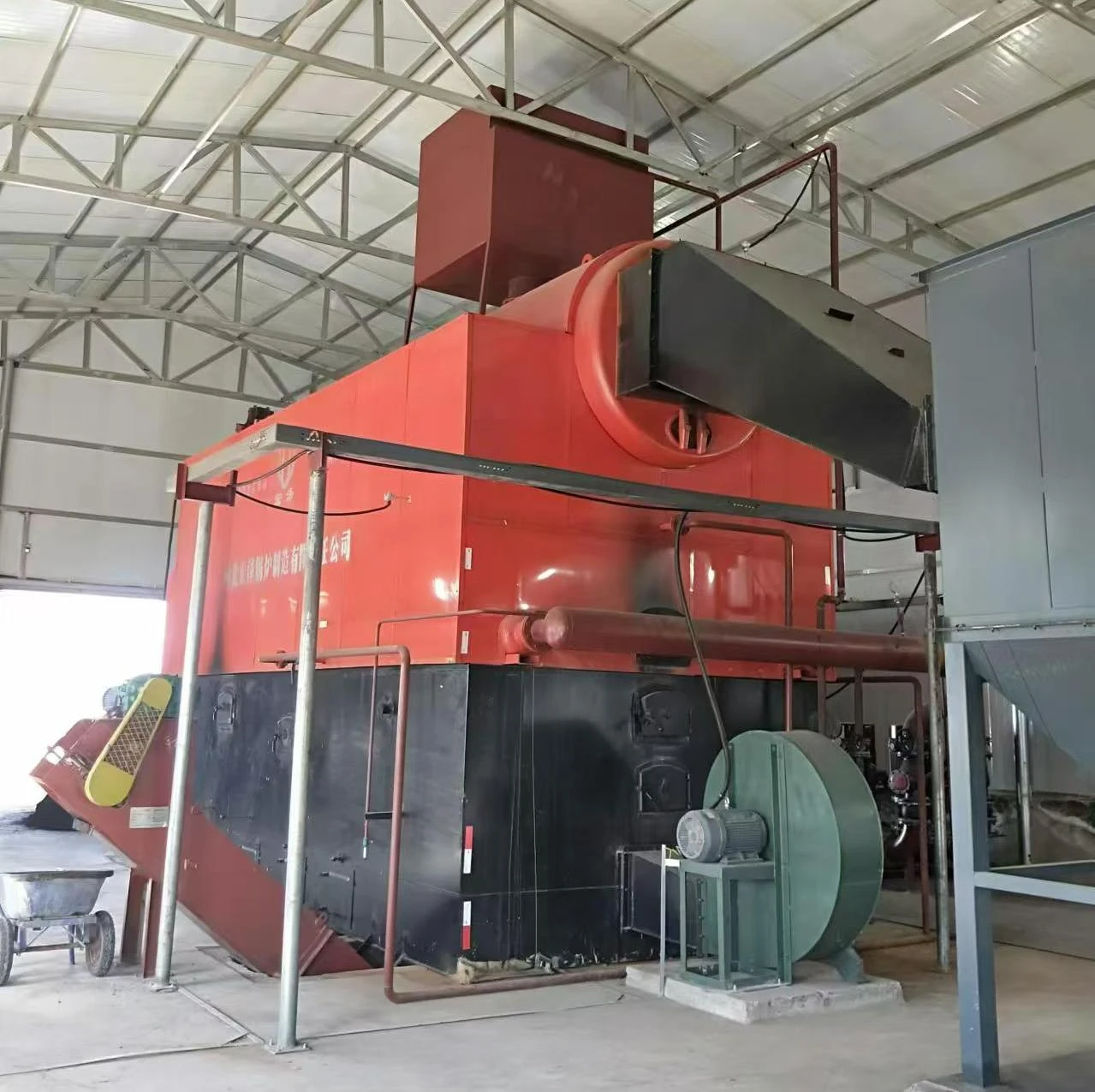
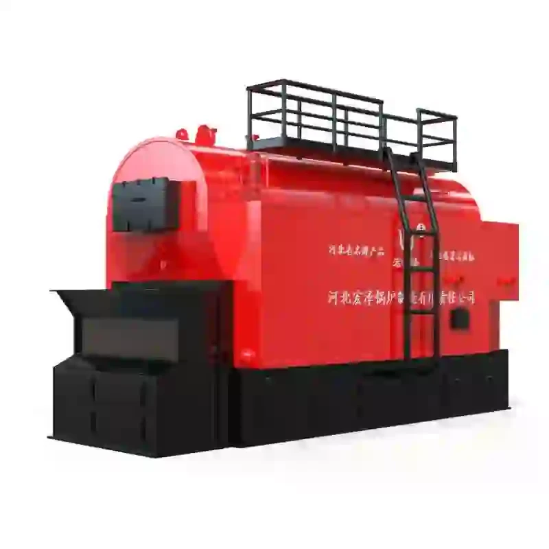
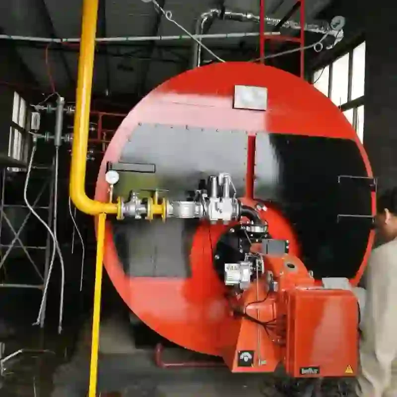
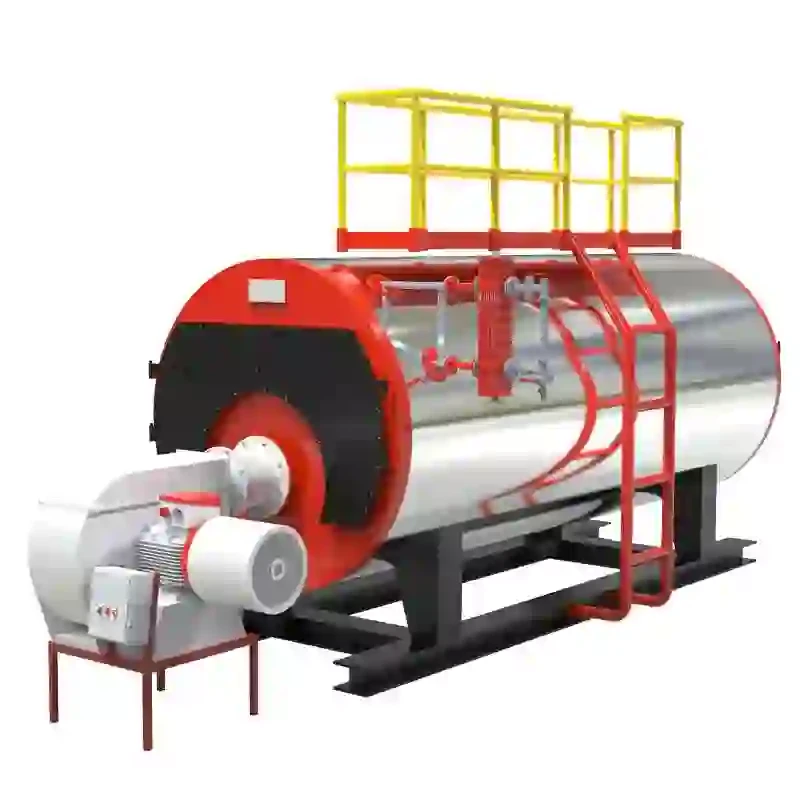
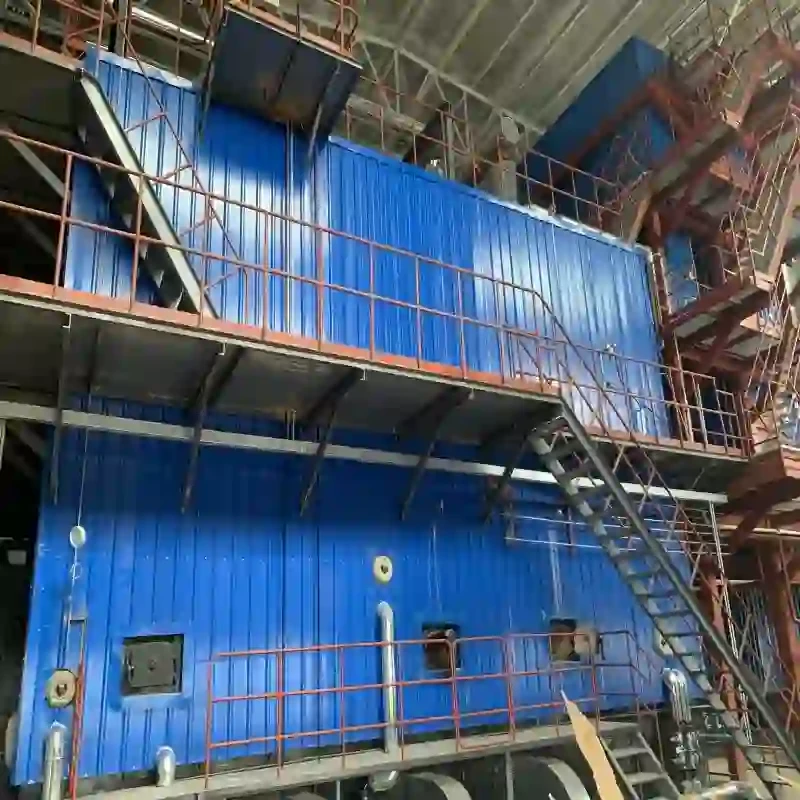
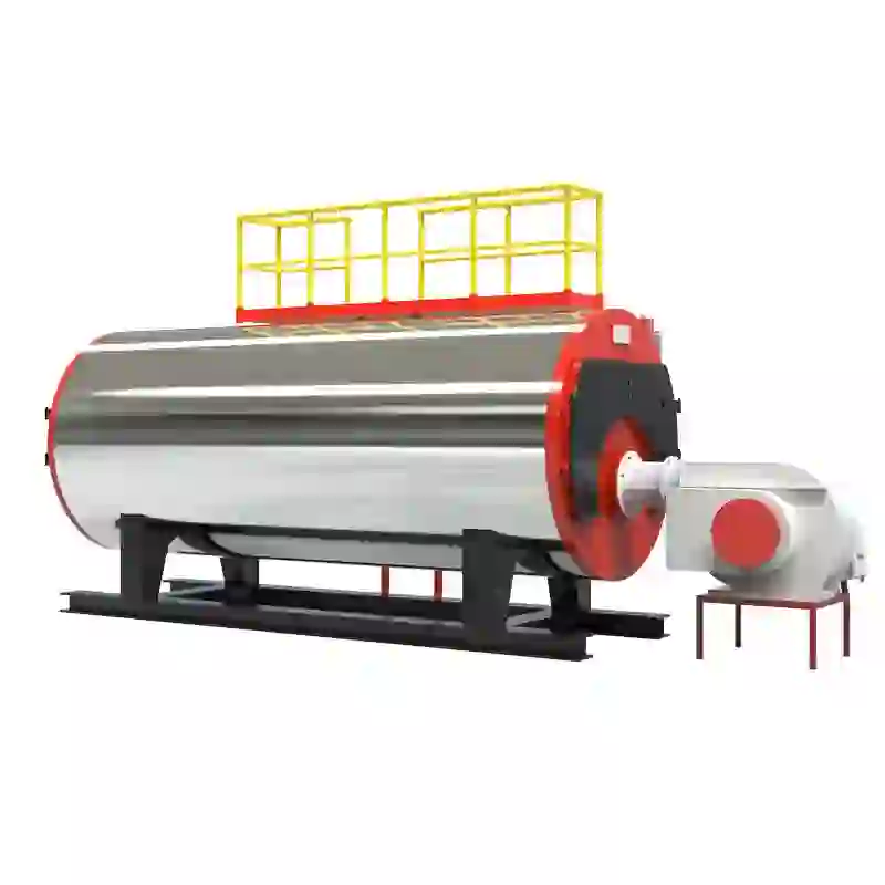
The boiler is the heart of the system where water is heated to produce steam. In many diagrams, the boiler is represented as a large rectangular shape, with arrows indicating the flow of water and steam. The burner, usually positioned at the base, is shown delivering fuel to the combustion chamber, where it ignites to generate heat.
steam boiler schematic diagram

A critical aspect of the schematic is the water supply system. It highlights how water is fed into the boiler from storage tanks or feed pumps, maintaining optimal water levels to ensure efficient steam production. The diagram illustrates various valves and controls that regulate water input, which is necessary to prevent boiler failure due to low water levels.
Safety devices are prominently featured in the schematic to emphasize their importance in boiler operation. Pressure relief valves, water level indicators, and temperature sensors are typically shown, ensuring that any abnormal conditions are quickly addressed. These components are vital for preventing accidents and ensuring the safe operation of the boiler.
Furthermore, the schematic may include auxiliary systems such as blowdown valves for removing impurities and steam traps for managing steam and condensate. These additional features improve the boiler's efficiency and longevity.
In summary, a steam boiler schematic diagram is an essential tool for understanding the operation of steam boilers. It provides a clear visualization of components and their relationships, facilitating better maintenance, troubleshooting, and safety measures. For engineers and operators, mastering the interpretation of these diagrams is crucial to ensuring efficient and safe steam production in industrial settings. Understanding these complex systems through schematic diagrams ultimately leads to enhanced operational efficiency and safety in steam boiler operations.
-
High-Efficiency Commercial Oil Fired Steam Boiler for Industry
NewsJul.30,2025
-
High-Efficiency Biomass Fired Thermal Oil Boiler Solutions
NewsJul.30,2025
-
High Efficiency Gas Fired Thermal Oil Boiler for Industrial Heating
NewsJul.29,2025
-
High-Efficiency Gas Fired Hot Water Boiler for Sale – Reliable & Affordable
NewsJul.29,2025
-
High Efficiency Biomass Fired Hot Water Boiler for Industrial and Commercial Use
NewsJul.29,2025
-
High-Efficiency Biomass Fired Hot Water Boiler for Industrial Use
NewsJul.28,2025
Related PRODUCTS


