Nov . 08, 2024 01:58 Back to list
Schematic Diagram of a Steam Boiler System and Its Components
Understanding the Steam Boiler Schematic Diagram
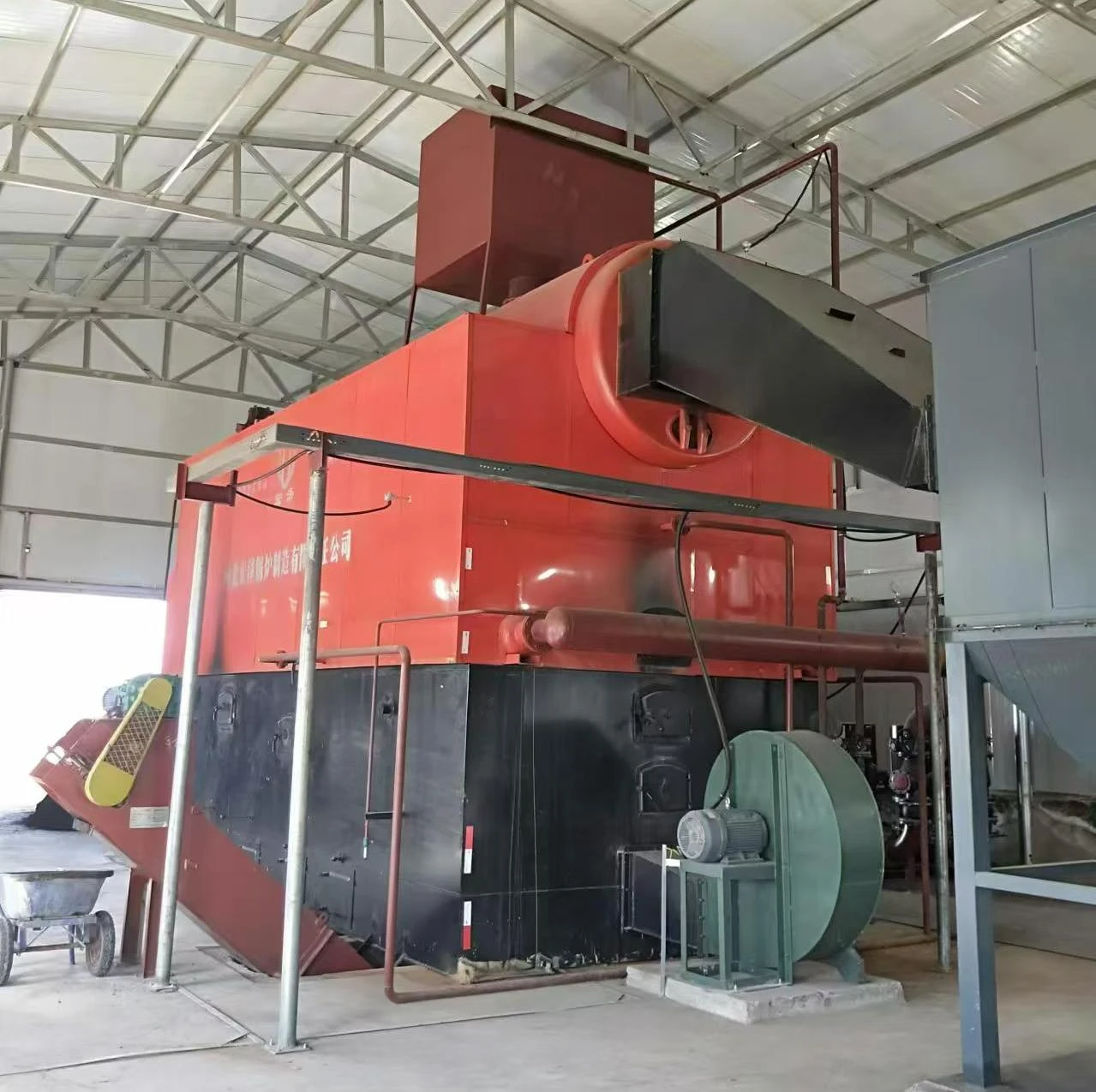
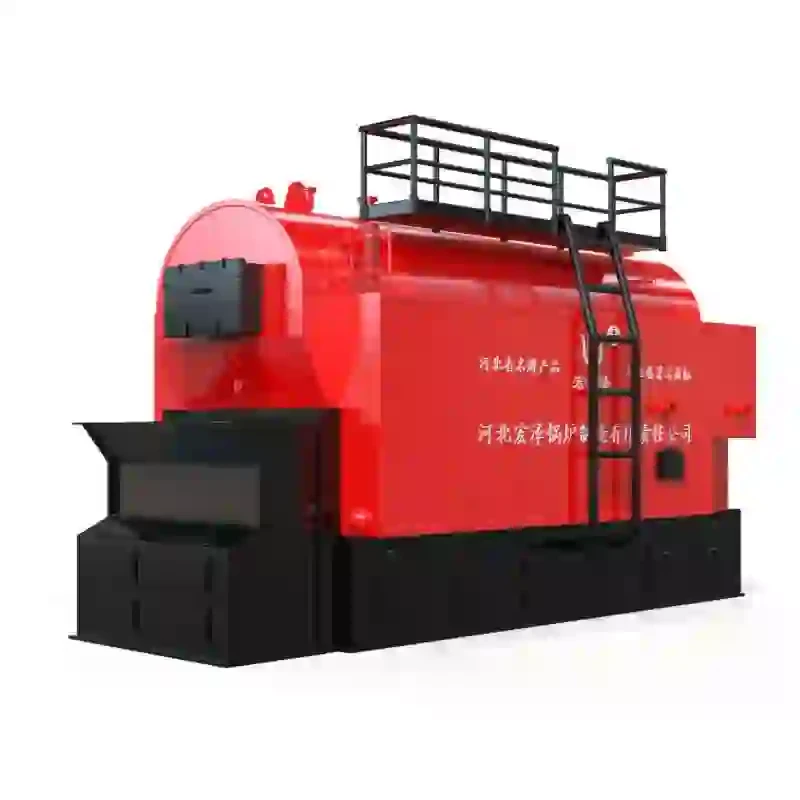
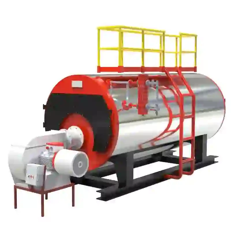
A steam boiler is an essential component in various industries, providing steam for heating, power generation, and various industrial processes. Understanding the schematic diagram of a steam boiler is crucial for operators, engineers, and maintenance personnel to ensure safe and efficient operation. This article will provide an overview of a typical steam boiler schematic diagram, detailing its components, functionalities, and the flow of processes involved.
At the heart of the steam boiler system are the boiler tubes, where water is heated to produce steam. In a schematic diagram, these tubes are typically represented as a series of lines or piping that show the flow direction. The heating process begins when water is fed into the boiler from a feedwater system, commonly equipped with a feedwater pump. This system must supply the correct amount of water, as maintaining an adequate water level is critical for safe operation and efficiency.
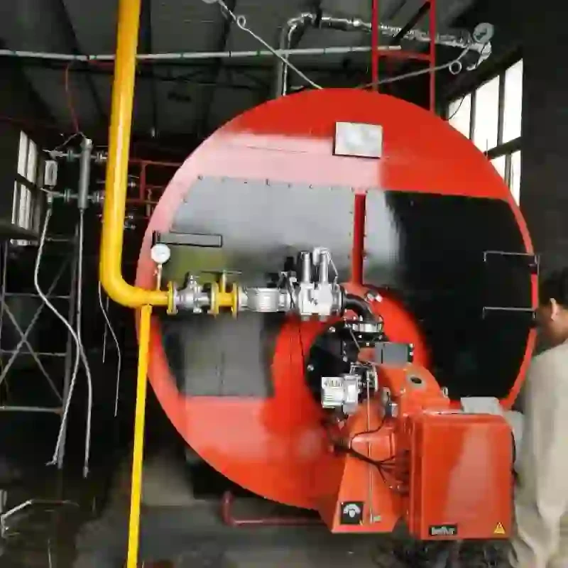
Once the water enters the boiler, it passes through various heating surfaces, often found within the furnace or combustion chamber. Here, fuel—such as natural gas, oil, or coal—is burned to generate heat. The schematic diagram illustrates fuel supply lines, along with combustion air inlets that ensure proper air-to-fuel ratios for combustion efficiency. The combustion process produces hot gases that flow through the boiler's heat exchanger tubes, transferring heat to the water inside the tubes, converting it to steam.
One of the central features represented in a steam boiler schematic is the steam drum. This is where the steam generated collects and separates from the water. As water is heated, it rises due to convection currents, and steam forms at the top of the drum. The schematic typically shows steam outlet lines leading away from the drum to the steam distribution network. Understanding the layout of these connections is vital for troubleshooting potential leaks or pressure drops in the system.
steam boiler schematic diagram

Moreover, the schematic diagram will also include safety devices such as pressure relief valves and water level indicators. Pressure relief valves are critical for the safety of the boiler, preventing excessive pressure buildup that could lead to catastrophic failure. Water level indicators, on the other hand, help operators monitor the water level and ensure it remains within safe limits.
Another crucial component shown in the schematic is the blowdown system. This system removes sediment and sludge that accumulate in the boiler over time, which could hinder efficiency and safety. Blowdown valves open to allow a controlled release of water, ensuring that the boiler continues to operate efficiently and safely. The diagram will often represent the blowdown lines and valves, indicating their routing toward a disposal system.
In addition to these components, the schematic will typically illustrate various pumps and controls essential for the operational integrity of the steam boiler. Control systems may include temperature and pressure sensors, which provide real-time data to operators. These data points are crucial for automatic controls that adjust fuel input and water supply to maintain optimal operating conditions.
One cannot overlook the importance of insulated piping and flue gas pathways indicated in the schematic. Insulated pipes help in maintaining heat and improving overall efficiency by reducing heat loss during steam transport. Flue gases produced during combustion need to be effectively vented away from the boiler, and the schematic will include flue gas stacks or exhaust systems that ensure proper emissions compliance and ventilation.
In conclusion, a steam boiler schematic diagram is a vital tool that provides insight into the complex processes and components involved in steam generation. By understanding the layout and functionality of each component—ranging from feedwater systems and combustion chambers to safety devices and control systems—operators can ensure efficient and safe operation. Regular training and familiarity with the schematic diagram empower personnel to identify potential issues, perform maintenance, and optimize the performance of steam boilers in industrial applications. This comprehensive understanding ultimately contributes to the reliability and efficiency of steam generation, ensuring the continuous operation of critical industrial processes.
-
High-Efficiency Commercial Oil Fired Steam Boiler for Industry
NewsJul.30,2025
-
High-Efficiency Biomass Fired Thermal Oil Boiler Solutions
NewsJul.30,2025
-
High Efficiency Gas Fired Thermal Oil Boiler for Industrial Heating
NewsJul.29,2025
-
High-Efficiency Gas Fired Hot Water Boiler for Sale – Reliable & Affordable
NewsJul.29,2025
-
High Efficiency Biomass Fired Hot Water Boiler for Industrial and Commercial Use
NewsJul.29,2025
-
High-Efficiency Biomass Fired Hot Water Boiler for Industrial Use
NewsJul.28,2025
Related PRODUCTS


