Sep . 22, 2024 13:32 Back to list
steam boiler schematic diagram
Understanding the Steam Boiler Schematic Diagram
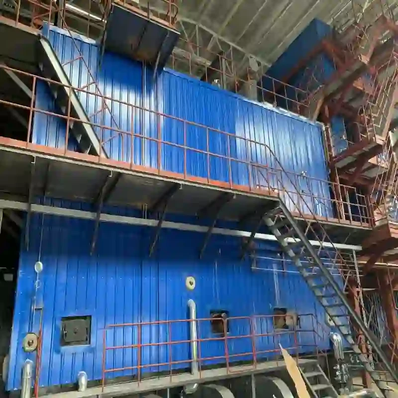
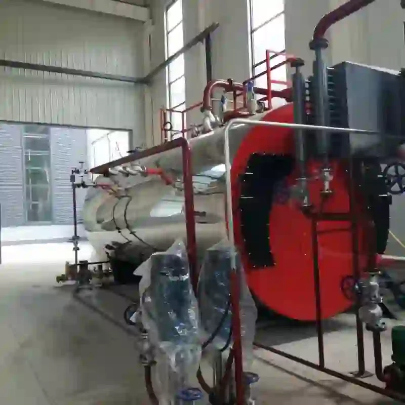
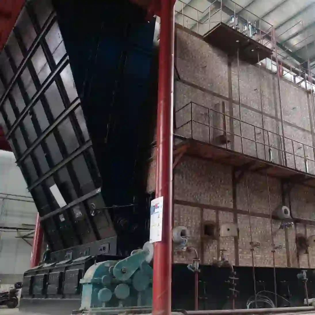
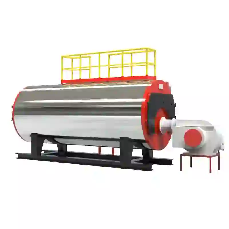
Steam boilers play a critical role in various industrial processes, serving as essential components for generating steam that is used for heating, power generation, and many other applications. To effectively understand how a steam boiler operates, one must familiarize themselves with its schematic diagram, which provides a clear visual representation of the system's components and flow paths.
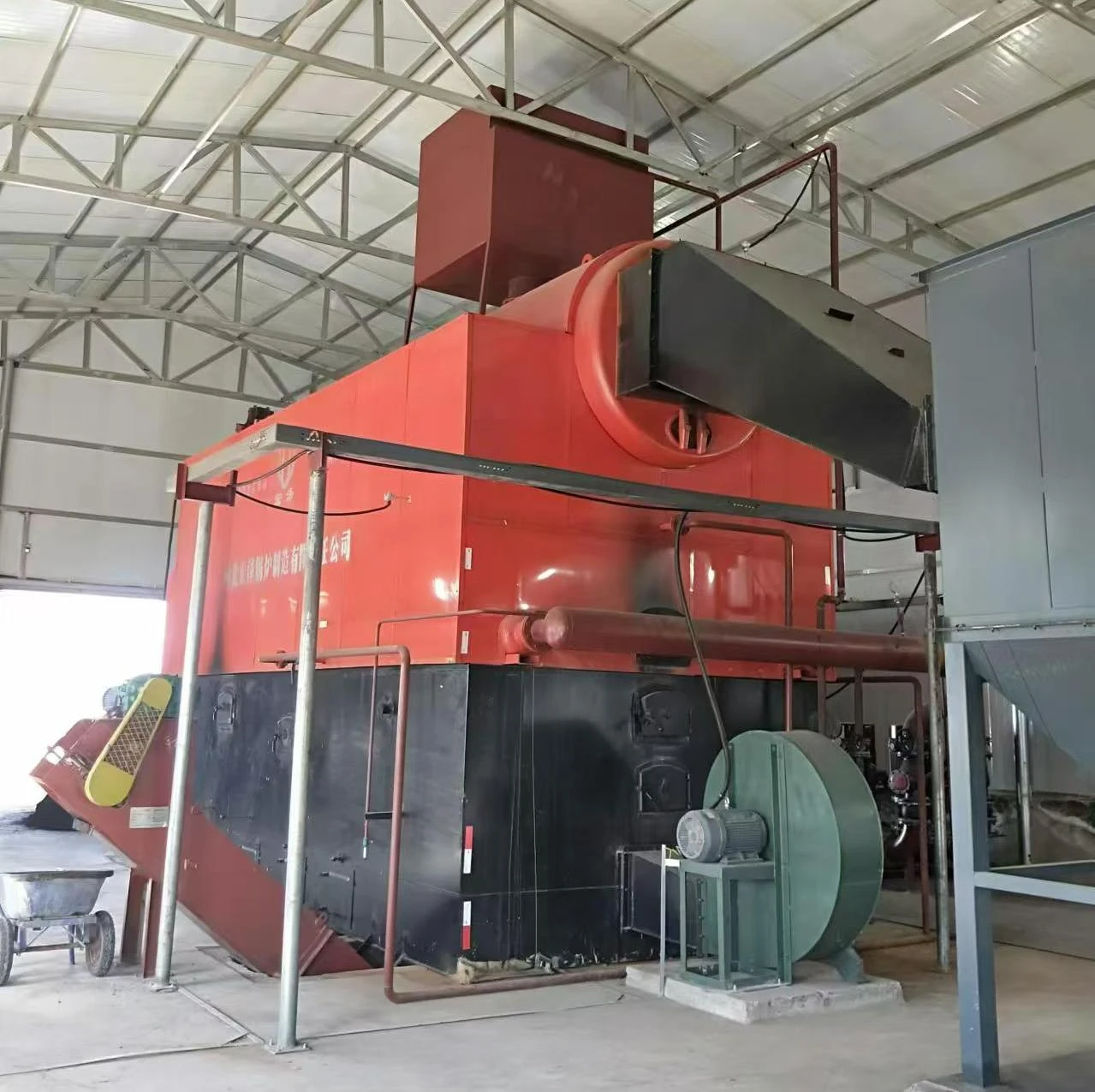
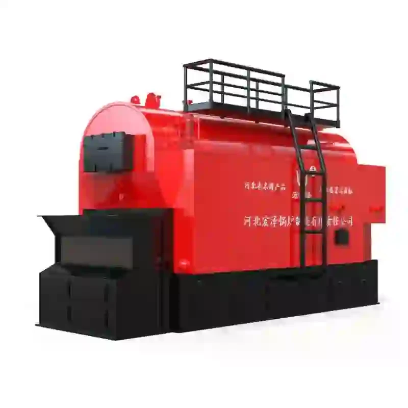
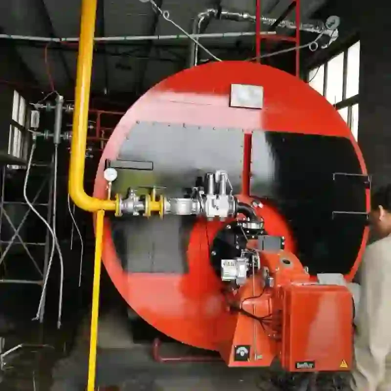
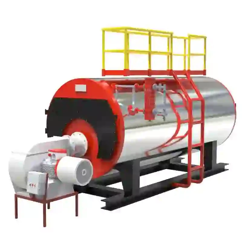
A typical steam boiler schematic diagram includes several key elements the boiler itself, feedwater systems, steam output, and various control and safety mechanisms. At the heart of the system is the boiler, where water is heated to produce steam. The diagram often depicts the combustion chamber, where fuel is burned to generate heat. This heat is transferred to the water through tubes or a heat exchange surface, leading to the conversion of water into steam.
Feedwater is introduced into the boiler from a feedwater line, which may include additional components such as water treatment systems to ensure water quality before it enters the boiler. Proper water quality is crucial, as impurities can lead to scaling or corrosion, potentially causing failures in the system.
steam boiler schematic diagram

Once the water is heated to its boiling point, steam is generated and collected in the steam drum or other storage units. The schematic diagram illustrates the flow of steam out to the intended applications, such as turbines for electricity generation, heating systems, or various industrial processes.
Control systems are also highlighted in the diagram, showcasing mechanisms like pressure regulators, temperature controls, and safety valves. These components ensure that the boiler operates within safe parameters, preventing dangerous conditions such as overpressure or overheating. The importance of such controls cannot be overstated, as they protect both the equipment and personnel working in proximity to the boiler.
In addition to these primary components, the visualization may include auxiliary systems, such as blow-down systems for removing sludge and impurities, flue gas systems that handle exhaust from the combustion process, and energy recovery systems that enhance overall efficiency.
In summary, a steam boiler schematic diagram is an invaluable tool for understanding the complexity of steam boiler systems. By studying this diagram, technicians and engineers can gain insights into the operation, maintenance, and troubleshooting of these essential systems, ensuring reliable and efficient heat and power generation in various industrial settings. Understanding each component's function within the schematic is key to optimizing boiler performance and ensuring safety standards are met.
-
High-Efficiency Commercial Oil Fired Steam Boiler for Industry
NewsJul.30,2025
-
High-Efficiency Biomass Fired Thermal Oil Boiler Solutions
NewsJul.30,2025
-
High Efficiency Gas Fired Thermal Oil Boiler for Industrial Heating
NewsJul.29,2025
-
High-Efficiency Gas Fired Hot Water Boiler for Sale – Reliable & Affordable
NewsJul.29,2025
-
High Efficiency Biomass Fired Hot Water Boiler for Industrial and Commercial Use
NewsJul.29,2025
-
High-Efficiency Biomass Fired Hot Water Boiler for Industrial Use
NewsJul.28,2025
Related PRODUCTS


