Sep . 22, 2024 04:34 Back to list
steam boiler system diagram
Understanding the Steam Boiler System Diagram
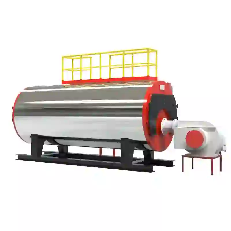
A steam boiler system is a critical component in many industrial applications, providing the necessary steam for heating processes, power generation, and various manufacturing processes. A steam boiler system diagram is essential for understanding how a boiler operates, the various components involved, and their interconnections. This article will outline the key elements of a steam boiler system diagram and explain their functions.
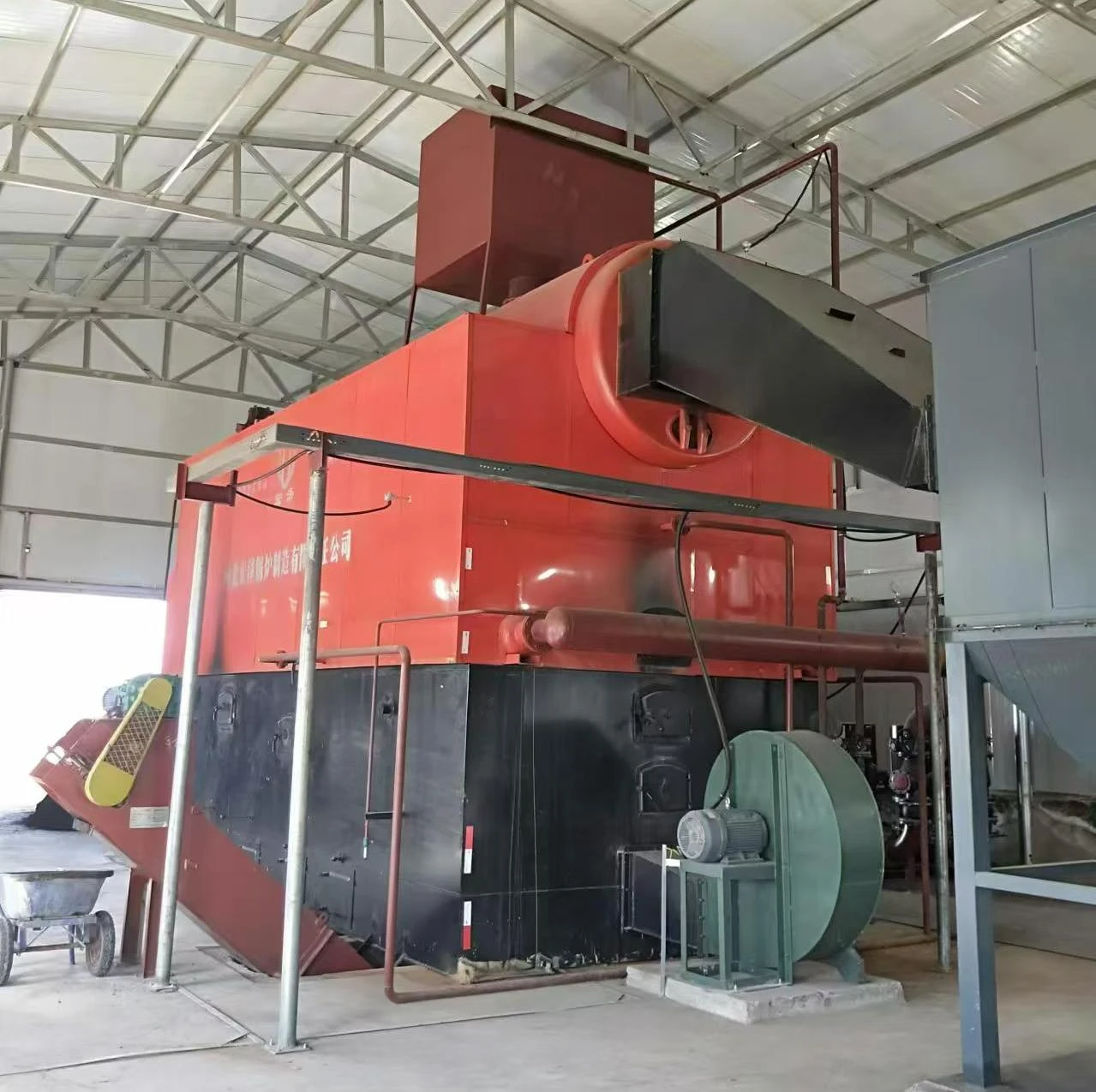
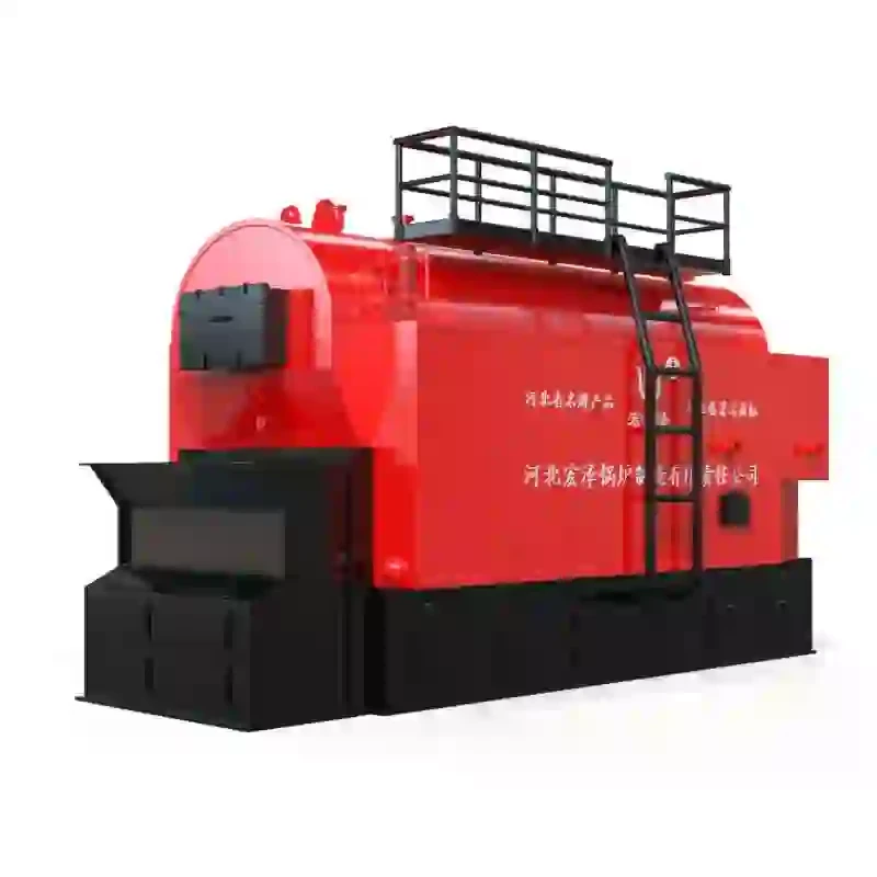
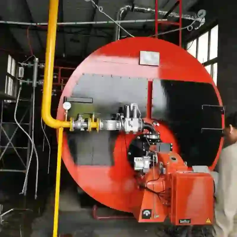
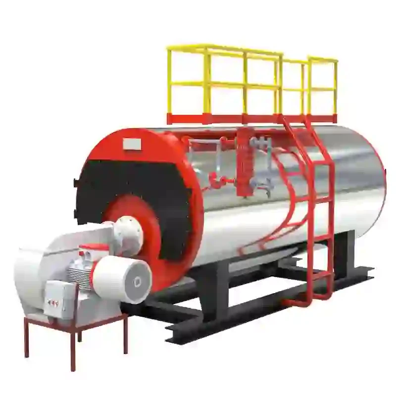
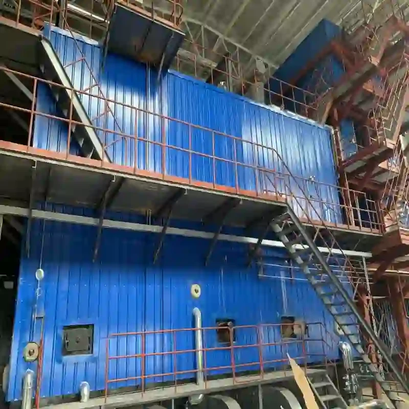
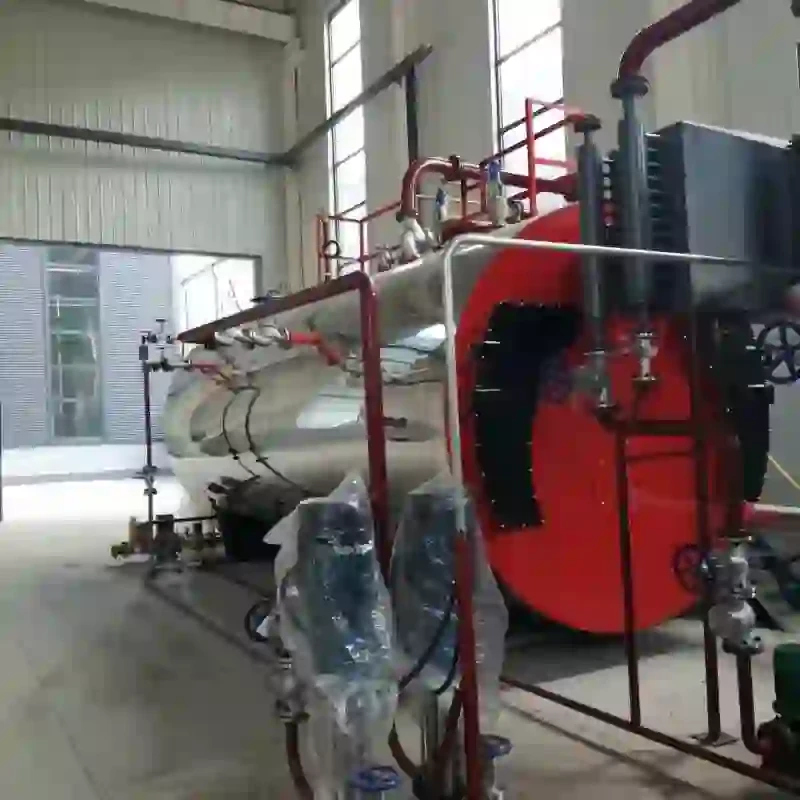
At the heart of any steam boiler system is the boiler itself. The boiler is a heavy-duty vessel designed to convert water into steam through the application of heat. The process begins with the introduction of water into the boiler, typically through a feedwater system. The feedwater enters the boiler under pressure and is heated by fuels such as coal, natural gas, or oil burned in the combustion chamber.
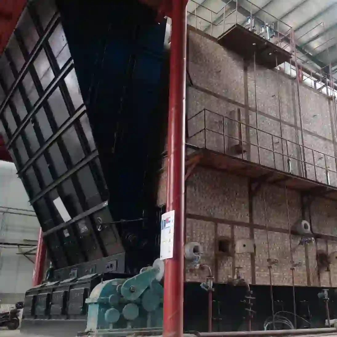
The combustion process takes place in the furnace, where the heat generated from burning fuel heats up the water within the boiler tubes. These tubes are integral to the heat exchange process, as they allow heat to transfer efficiently from the combustion gases to the water. A boiler diagram will often depict the configuration of these tubes, which may be organized in a variety of ways, such as firetube, watertube, or a combination of both.
As water is heated, it transforms into steam. The steam produced accumulates in the steam drum, a large vessel designed to store high-pressure steam before it is directed to its application. The pressure levels within the steam drum are crucial to maintain, as they influence the steam's efficiency and quality. Safety devices such as pressure relief valves are depicted in the system diagram, ensuring the system operates within safe limits and preventing potential explosions due to overpressure.
steam boiler system diagram

Following the steam drum, the steam is routed through a series of pipes to the end users, such as turbines or heat exchangers
. A steam boiler system diagram illustrates these piping systems, through which steam travels, often highlighting necessary components like control valves and flow meters that regulate steam flow and pressure.In addition to the primary components mentioned, a steam boiler system includes auxiliary equipment. Water treatment systems are essential to condition the feedwater, removing impurities that can cause scaling and corrosion within the boiler. An economizer may also be part of the system diagram; this heat recovery device captures waste heat from the flue gases, improving overall energy efficiency by preheating the incoming feedwater.
Another significant aspect of a steam boiler system is its emission control features. The combustion process produces gases that can be harmful to the environment, so systems such as scrubbers or electrostatic precipitators are often included to reduce emissions. The steam boiler system diagram will typically represent these components, demonstrating how they integrate into the overall system.
In conclusion, a steam boiler system diagram serves as a vital tool for understanding the complex interactions within the steam generation process. By illustrating the components such as the boiler, feedwater system, steam drum, piping, and auxiliary equipment, it provides insight into how steam is generated, controlled, and utilized in various applications. Understanding this system is crucial for maintenance, operation, and optimization of efficiency in industrial processes that rely on steam.
-
High-Efficiency Commercial Oil Fired Steam Boiler for Industry
NewsJul.30,2025
-
High-Efficiency Biomass Fired Thermal Oil Boiler Solutions
NewsJul.30,2025
-
High Efficiency Gas Fired Thermal Oil Boiler for Industrial Heating
NewsJul.29,2025
-
High-Efficiency Gas Fired Hot Water Boiler for Sale – Reliable & Affordable
NewsJul.29,2025
-
High Efficiency Biomass Fired Hot Water Boiler for Industrial and Commercial Use
NewsJul.29,2025
-
High-Efficiency Biomass Fired Hot Water Boiler for Industrial Use
NewsJul.28,2025
Related PRODUCTS


