Nov . 12, 2024 19:03 Back to list
steam boiler system schematic diagram
Understanding the Steam Boiler System Schematic Diagram
A steam boiler system is a crucial component in many industrial processes, and understanding its schematic diagram is essential for engineers and technicians working within this field. This article will explore the components, functionality, and significance of steam boiler systems as represented in their schematic diagrams.
What is a Steam Boiler?
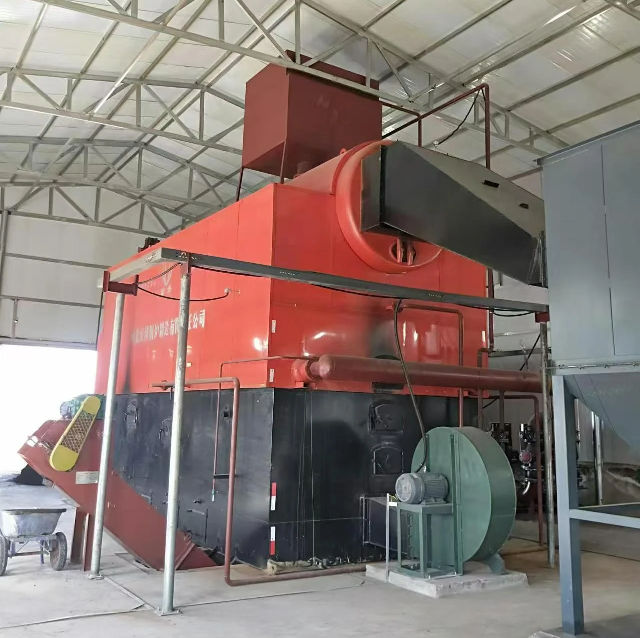
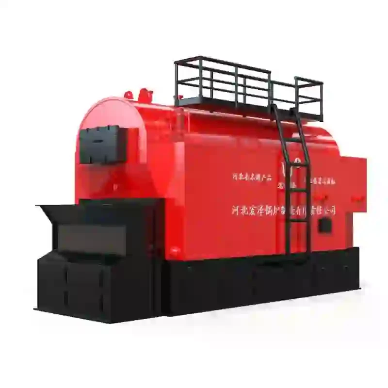
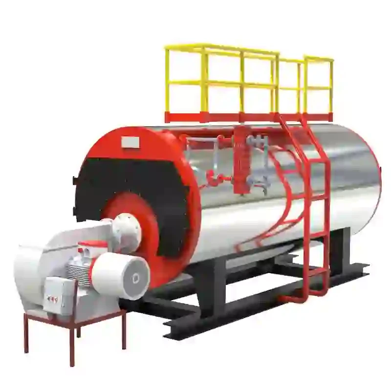
A steam boiler is a closed vessel that heats water to create steam by burning fuel or using electrical energy. The steam produced is then used for various applications, including powering turbines, heating buildings, and supporting processes in manufacturing. The efficiency and functionality of a steam boiler system make it an integral part of many industries, from energy production to pharmaceuticals.
Components of a Steam Boiler System
A steam boiler system is made up of several components that work together to ensure efficient steam generation. In a typical schematic diagram, you will find the following key parts
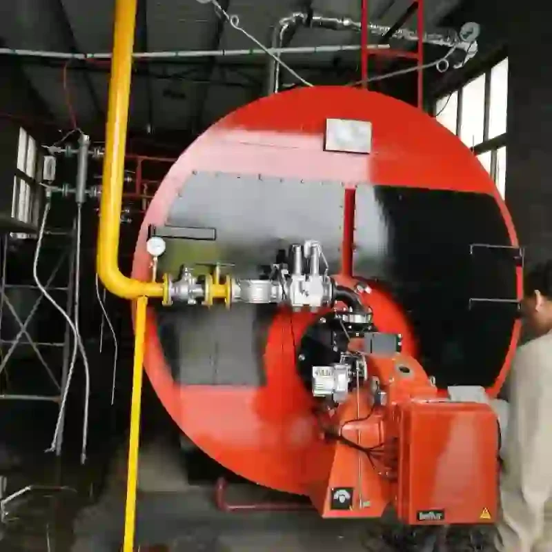
1. Boiler The central component where water is heated to produce steam. It includes a combustion chamber and a heat exchanger. 2. Burner Responsible for supplying the fuel into the combustion chamber. The burner can be operated with various fuel types, including natural gas, oil, or coal.
3. Water Supply System This includes pumps and valves that supply water to the boiler. The water must be treated to prevent scale and corrosion.
4. Steam Drum A cylindrical vessel that separates steam from water. It ensures that only steam is sent out for use, while the remaining water recirculates within the system.
6. Pressure Control System Regulates the pressure within the boiler to optimize performance and prevent hazardous situations.
steam boiler system schematic diagram
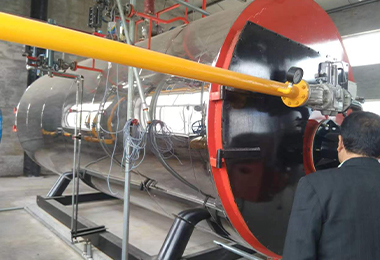
7. Feedwater Heater Preheats the water before it enters the boiler, enhancing the overall efficiency of the system.
8. Condensate Return System Collects and returns the condensed steam back to the boiler, reducing water and energy wastage.
Understanding the Schematic Diagram
The schematic diagram of a steam boiler system typically presents a simplified visual representation of the components and their interconnections. Lines and symbols are used to illustrate the flow of water, steam, and fuel throughout the system.
In the diagram, various valves, gauges, and flow meters are illustrated to indicate where operations can be controlled. For example, pressure gauges might be shown on the steam line to monitor the operation and ensure safe levels are maintained. Safety valves are also depicted to show where excess pressure might be released to prevent explosions.
Different symbols represent pumps, motors, and electrical components, which feed into the boiler’s controls. The arrows indicate the direction of flow, illustrating the path from the water supply, through heating, steam generation, and back to the condensate return.
Importance of Understanding the Schematic Diagram
For anyone involved in the operation and maintenance of steam boiler systems, a solid understanding of the schematic diagram is imperative. It enhances troubleshooting efforts by allowing technicians to pinpoint potential issues quickly. Being able to read and interpret the schematic helps in identifying malfunctioning components, enabling prompt repairs that minimize downtime.
Moreover, an accurate understanding ensures adherence to safety protocols. Steam boilers operate under high pressure and temperature conditions; hence, recognizing pressure control systems and safety valves on the schematic assists operators in maintaining a safe working environment.
Conclusion
Steam boiler systems are an essential aspect of countless industrial operations, and their schematic diagrams provide invaluable information about their functioning. By breaking down the key components and understanding their interactions, operators can ensure efficient operation, enhance safety, and facilitate effective maintenance. As technology evolves, the design and operations of steam boilers will continue to advance, but a fundamental grasp of their schematic representations will remain vital to any professional in the field.
-
High-Efficiency Commercial Oil Fired Steam Boiler for Industry
NewsJul.30,2025
-
High-Efficiency Biomass Fired Thermal Oil Boiler Solutions
NewsJul.30,2025
-
High Efficiency Gas Fired Thermal Oil Boiler for Industrial Heating
NewsJul.29,2025
-
High-Efficiency Gas Fired Hot Water Boiler for Sale – Reliable & Affordable
NewsJul.29,2025
-
High Efficiency Biomass Fired Hot Water Boiler for Industrial and Commercial Use
NewsJul.29,2025
-
High-Efficiency Biomass Fired Hot Water Boiler for Industrial Use
NewsJul.28,2025
Related PRODUCTS


