Nov . 22, 2024 16:15 Back to list
steam boiler system schematic diagram
Understanding Steam Boiler System Schematic Diagrams
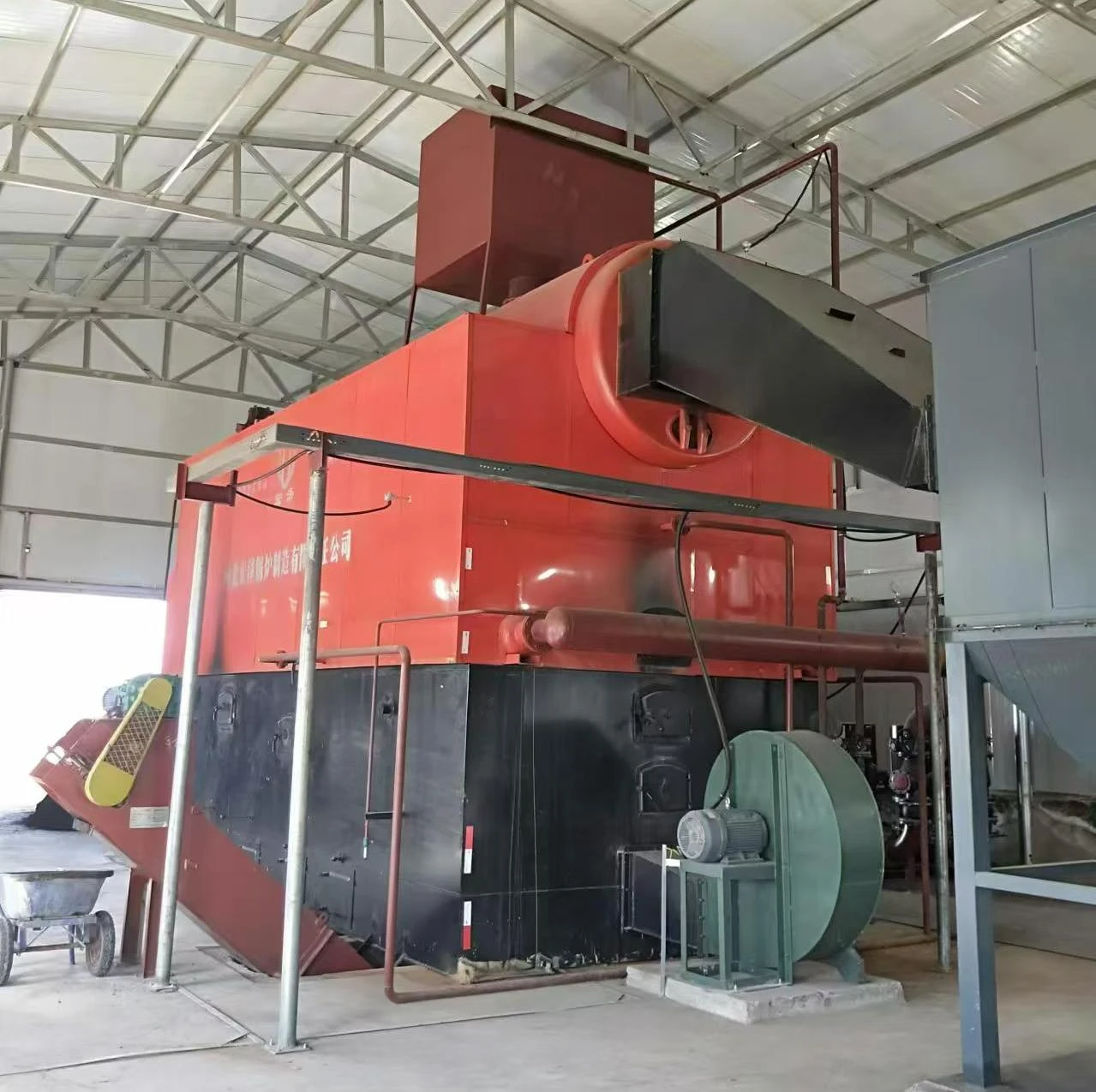
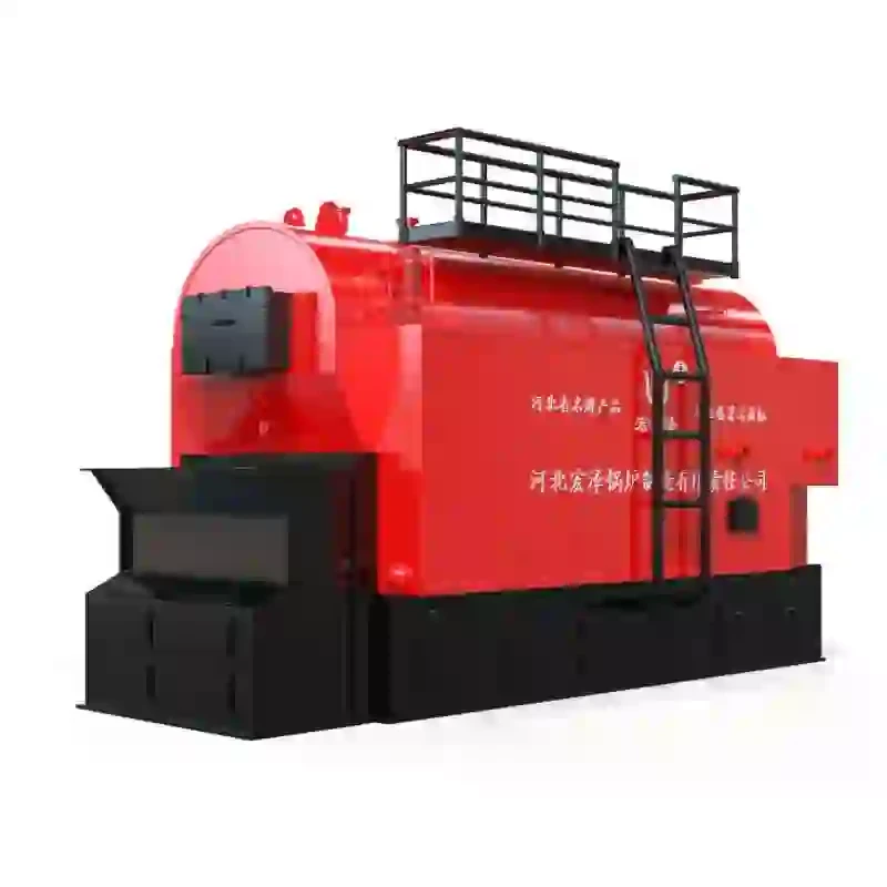
A steam boiler system schematic diagram is an essential tool for engineers and maintenance personnel involved in the design, operation, and troubleshooting of steam-generating systems. This diagram visually represents the components of a steam boiler system, showcasing how they interconnect and function to produce steam for various industrial applications.
Components of a Steam Boiler Schematic Diagram
At the heart of any steam boiler system is the boiler itself, where water is heated to produce steam. The schematic diagram typically illustrates the following key components
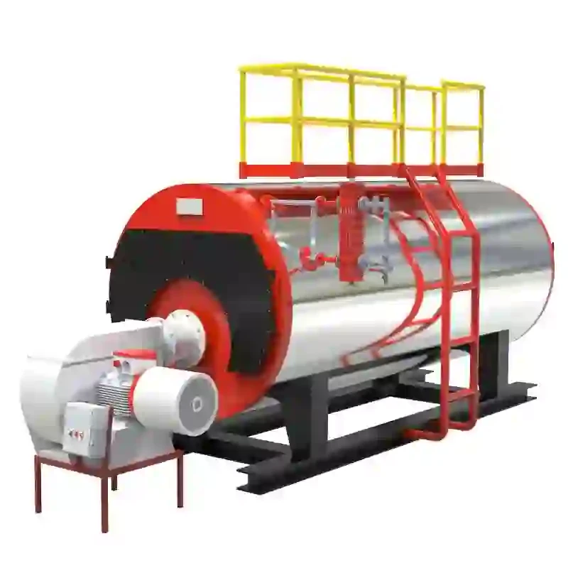
1. Boiler The primary vessel where water is heated. Different boiler types exist, including fire-tube, water-tube, and electric boilers, each having unique operational mechanics.
2. Heat Exchanger Some systems feature a heat exchanger that allows heat transfer from hot gases to water without direct contact, optimizing efficiency and minimizing contamination.
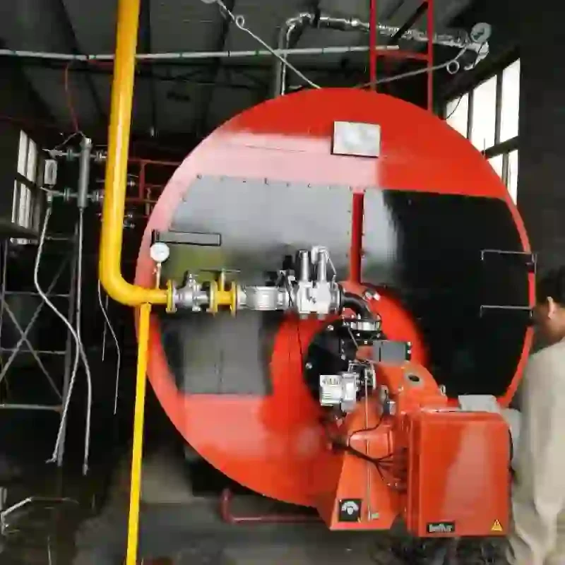
3. Burner This component fuels the system, whether it relies on natural gas, oil, or electricity. The burner ignites the fuel to generate heat, which is then transferred to the water in the boiler.
4. Feed Water System This includes pumps and valves that ensure a consistent supply of feed water to the boiler. The quality and temperature of the feed water are critical for efficient steam generation.
steam boiler system schematic diagram
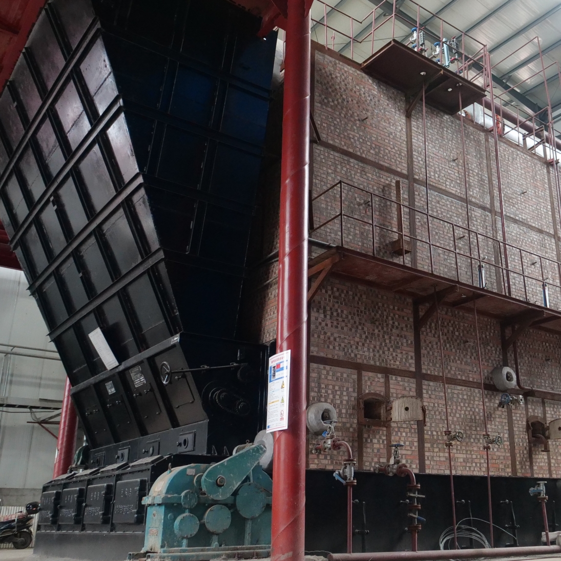
5. Steam Drum and Separator In larger systems, steam drums separate steam from water, ensuring that only dry steam is used for process heat or power generation.
6. Condensate Return System This system collects the steam that has been used and condensed back to water, returning it to the boiler for reuse, thus improving efficiency.
7. Controls and Instrumentation Schematic diagrams also indicate various control devices like pressure gauges, temperature sensors, and flow meters that monitor the system's performance and safety.
Importance of Schematic Diagrams
Schematic diagrams play a crucial role in training operators and technicians. They provide a clear visual reference that aids in understanding the system's layout and functionality. For troubleshooting, these diagrams help identify potential issues by revealing the interconnections between components.
Additionally, during routine maintenance or emergency repairs, having a schematic diagram can significantly reduce downtime. It allows technicians to quickly locate valves, shut-off points, and other critical components, streamlining the repair process.
Conclusion
In conclusion, a steam boiler system schematic diagram serves as a vital resource in the management and operation of steam boilers. By illustrating the various components and their interactions, these diagrams facilitate efficient training, troubleshooting, and maintenance. Understanding these schematics is essential for anyone involved in the operation of steam systems, ensuring safety and efficiency in industrial processes. As technology advances, the need for clear and accurate schematic diagrams remains critical in maintaining the integrity and performance of steam boiler systems.
-
High-Efficiency Commercial Oil Fired Steam Boiler for Industry
NewsJul.30,2025
-
High-Efficiency Biomass Fired Thermal Oil Boiler Solutions
NewsJul.30,2025
-
High Efficiency Gas Fired Thermal Oil Boiler for Industrial Heating
NewsJul.29,2025
-
High-Efficiency Gas Fired Hot Water Boiler for Sale – Reliable & Affordable
NewsJul.29,2025
-
High Efficiency Biomass Fired Hot Water Boiler for Industrial and Commercial Use
NewsJul.29,2025
-
High-Efficiency Biomass Fired Hot Water Boiler for Industrial Use
NewsJul.28,2025
Related PRODUCTS


