Nov . 26, 2024 21:23 Back to list
Schematic Diagram of a Steam Boiler System for Efficient Operation and Maintenance
Understanding the Steam Boiler System Schematic Diagram
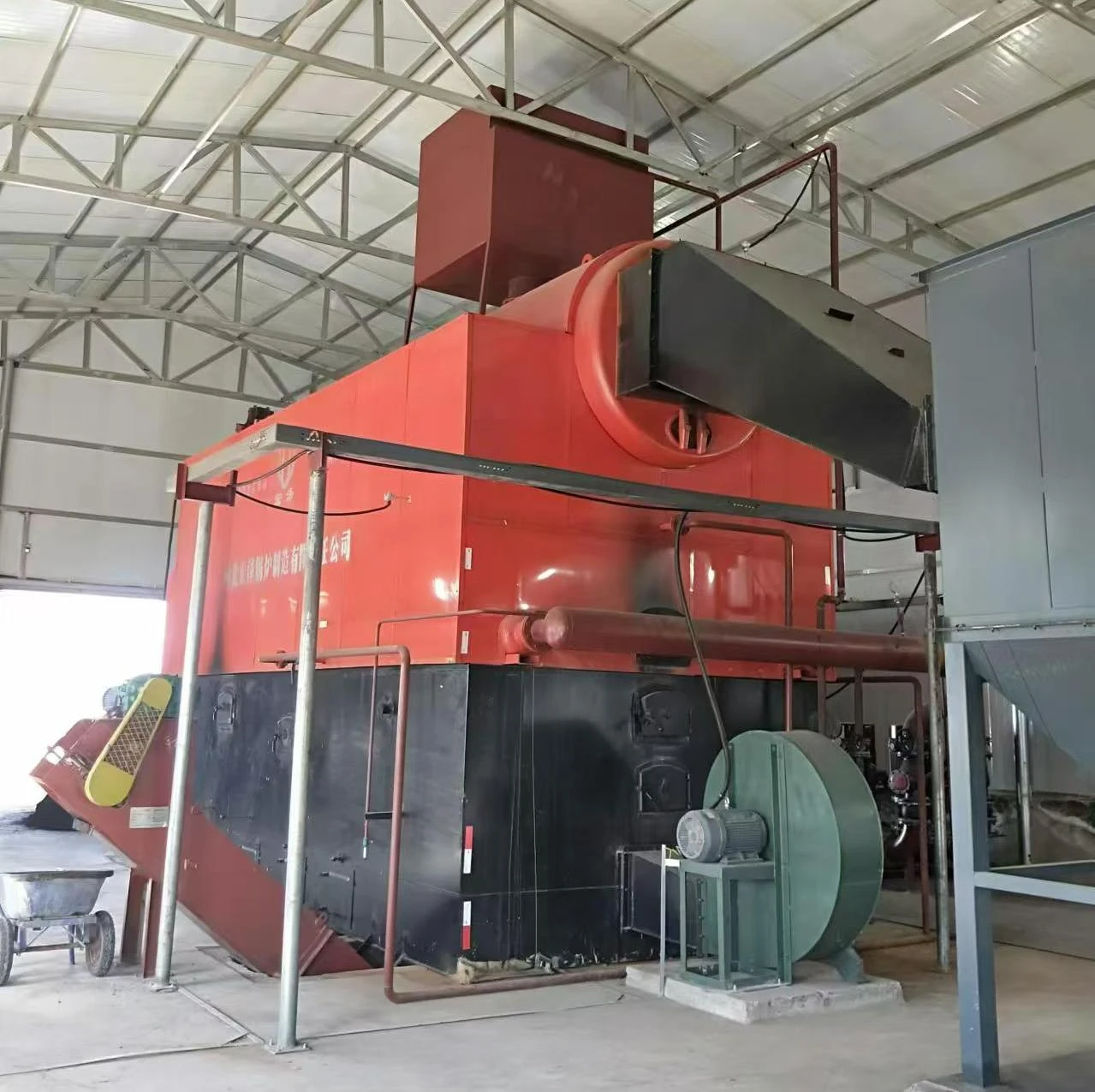
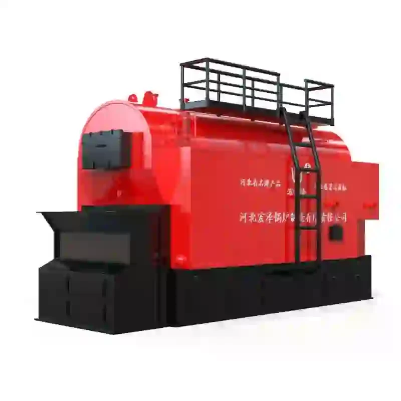
A steam boiler system schematic diagram serves as an essential tool for understanding the complexities of steam generation and its associated systems in industrial settings. This diagram visually represents the various components, interconnections, and process flow involved in a steam boiler setup. Steam boilers play a critical role in many industries, including power generation, food processing, and chemical manufacturing, making it vital for engineers and technicians to grasp their operational intricacies.
Components of a Steam Boiler System
At the heart of any steam boiler system is the boiler itself, which converts water into steam through the application of heat. The schematic diagram typically illustrates major components including
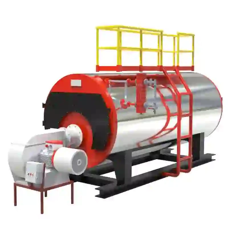
1. Boiler The main piece of apparatus where water is heated to produce steam. Various types exist, including fire-tube and water-tube boilers, each with its operational characteristics.
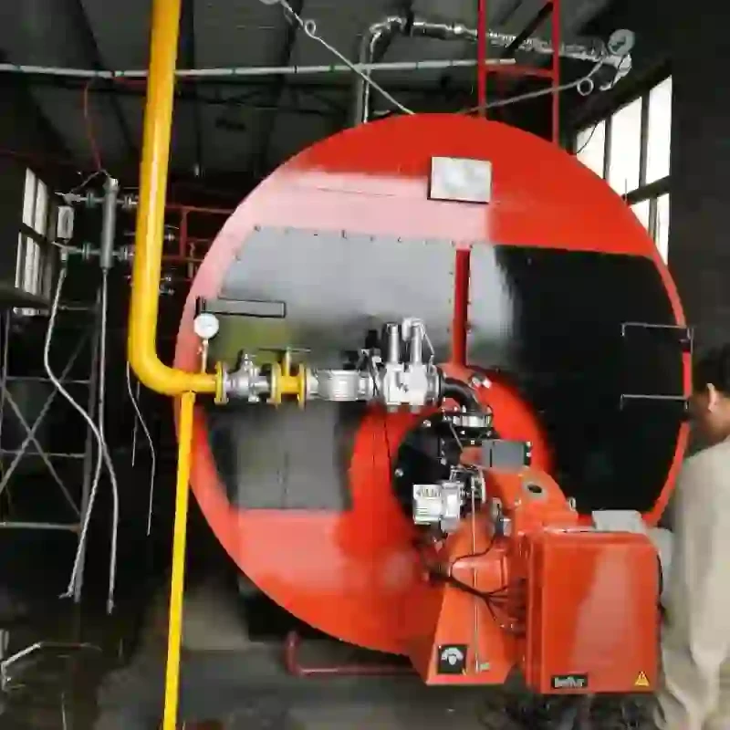
2. Burner Responsible for igniting the fuel that generates heat within the boiler. The schematic shows the fuel supply lines linked to the burner, highlighting the types of fuels used—such as natural gas, oil, or coal.
3. Water Supply System This component is crucial for maintaining the appropriate water level in the boiler. The schematic often includes water feed pumps and valves, indicating how water is introduced into the system and the necessary controls for maintaining optimal levels.
4. Steam Drum A large vessel where steam separates from the water. The diagram demonstrates how steam rises to the top while the water stays below, often alongside automatic level controls to maintain balance.
6. Condensate Return System After steam is used, it condenses back into water, which then needs to return to the boiler. This system often includes condensate pumps and storage tanks, crucial for efficiency and resource conservation.
steam boiler system schematic diagram

7. Flue Gas System The schematic illustrates the path for flue gases created from the combustion process, often via a stack or chimney, ensuring that emissions are safely released and environmental regulations adhered to.
Understanding Flow Paths
In a schematic diagram, flow paths are represented by arrows, indicating the progression of water, steam, and gases through the system. Understanding these pathways helps in troubleshooting and optimizing boiler performance. For instance, recognizing the flow of steam to various heating applications, such as turbines or heat exchangers, is crucial for ensuring that the system is working efficiently.
Importance of Control Systems
Control systems are integral to the operation of steam boiler systems and are depicted strategically within the schematic. These can include automated control panels where operators can monitor and adjust parameters such as temperature, pressure, and flow rates. Advanced systems may also incorporate digital sensors and IoT technologies to enhance operation reliability and facilitate remote monitoring.
Maintenance and Troubleshooting
An understanding of the steam boiler system schematic diagram is vital for maintenance and troubleshooting. By familiarizing oneself with the layout and functionality of each component, maintenance personnel can more effectively diagnose issues, recommend repairs, or perform routine checks. For instance, if the boiler experiences low pressure, personnel can trace back through the schematic to identify potential causes, such as pump failures or blockages in the feedwater line.
Conclusion
In summary, a steam boiler system schematic diagram is not only a representation of the physical components and their connections, but it also serves as a functional roadmap for understanding steam generation processes. Mastery of this diagram is essential for anyone involved in boiler operation, design, or maintenance. With steam boilers being fundamental to many industrial processes, possessing a detailed comprehension of their operation through these schematic representations is crucial for safety, efficiency, and productivity. This knowledge not only supports effective day-to-day operations but also promotes innovation and improvements in boiler technology.
-
Efficient Biomass Fired Hot Water Boiler | AI Heating Solution
NewsAug.01,2025
-
High-Efficiency Gas Thermal Oil Boilers | HPT Models
NewsJul.31,2025
-
Oil Fired Hot Water Boilers Sale - High Efficiency & Affordable
NewsJul.31,2025
-
High-Efficiency Commercial Oil Fired Steam Boiler for Industry
NewsJul.30,2025
-
High-Efficiency Biomass Fired Thermal Oil Boiler Solutions
NewsJul.30,2025
-
High Efficiency Gas Fired Thermal Oil Boiler for Industrial Heating
NewsJul.29,2025
Related PRODUCTS


